1024-Bit, 1-Wire EEPROM
16
15
2
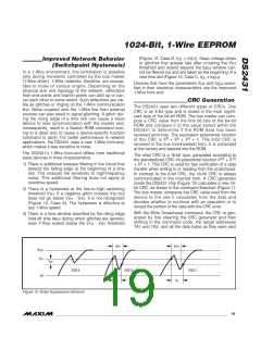
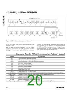
POLYNOMIAL = X + X + X + 1
1ST
2ND
3RD
4TH
5TH
6TH
7TH
8TH
STAGE
STAGE
STAGE
STAGE
STAGE
STAGE
STAGE
STAGE
0
1
2
3
4
5
6
7
X
X
X
X
X
X
X
X
DS2431
9TH
STAGE
10TH
STAGE
11TH
STAGE
12TH
STAGE
13TH
STAGE
14TH
STAGE
15TH
STAGE
16TH
STAGE
8
9
10
11
12
13
14
15
16
CRC OUTPUT
X
X
X
X
X
X
X
X
X
INPUT DATA
Figure 13. CRC-16 Hardware Description and Polynomial
by the bus master. The DS2431 transmits this CRC only
if E[2:0] = 111b.
TA1 and TA2, the E/S byte, and the scratchpad data as
they were sent by the DS2431. The DS2431 transmits
this CRC only if the reading continues through the end
of the scratchpad. For more information on generating
CRC values, refer to Application Note 27.
With the Read Scratchpad command, the CRC is gen-
erated by first clearing the CRC generator and then
shifting in the command code, the target addresses
Command-Specific 1-Wire Communication Protocol—Legend
SYMBOL
RST
DESCRIPTION
1-Wire reset pulse generated by master.
PD
1-Wire presence pulse generated by slave.
Select
Command and data to satisfy the ROM function protocol.
Command "Write Scratchpad."
WS
RS
Command "Read Scratchpad."
CPS
Command "Copy Scratchpad."
RM
Command "Read Memory."
TA
Target address TA1, TA2.
TA-E/S
Target address TA1, TA2 with E/S byte.
<8–T[2:0] bytes>
<Data to EOM>
CRC-16
FF Loop
AA Loop
Programming
Transfer of as many bytes as needed to reach the end of the scratchpad for a given target address.
Transfer of as many data bytes as are needed to reach the end of the memory.
Transfer of an inverted CRC-16.
Indefinite loop where the master reads FF bytes.
Indefinite loop where the master reads AA bytes.
Data transfer to EEPROM; no activity on the 1-Wire bus permitted during this time.
20 ______________________________________________________________________________________

 MAXIM [ MAXIM INTEGRATED PRODUCTS ]