1024-Bit, 1-Wire EEPROM
DS2431
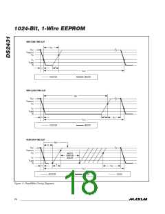
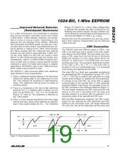
(Figure 12, Case B, t < t
). Deep voltage drops
GL
REH
Improved Network Behavior
(Switchpoint Hysteresis)
or glitches that appear late after crossing the V
TH
threshold and extend beyond the t
window can-
REH
In a 1-Wire environment, line termination is possible
only during transients controlled by the bus master
(1-Wire driver). 1-Wire networks, therefore, are suscep-
tible to noise of various origins. Depending on the
physical size and topology of the network, reflections
from end points and branch points can add up or can-
cel each other to some extent. Such reflections are visi-
ble as glitches or ringing on the 1-Wire communication
line. Noise coupled onto the 1-Wire line from external
sources can also result in signal glitching. A glitch dur-
ing the rising edge of a time slot can cause a slave
device to lose synchronization with the master and,
consequently, result in a Search ROM command com-
ing to a dead end or cause a device-specific function
command to abort. For better performance in network
applications, the DS2431 uses a new 1-Wire front-end,
which makes it less sensitive to noise.
not be filtered out and are taken as the beginning of a
new time slot (Figure 12, Case C, t ≥ t ).
GL
REH
Devices that have the parameters V
and t
speci-
REH
HY
fied in their electrical characteristics use the improved
1-Wire front-end.
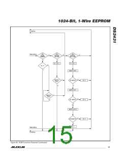
CRC Generation
The DS2431 uses two different types of CRCs. One
CRC is an 8-bit type and is stored in the most signifi-
cant byte of the 64-bit ROM. The bus master can com-
pute a CRC value from the first 56 bits of the 64-bit
ROM and compare it to the value stored within the
DS2431 to determine if the ROM data has been
received error-free. The equivalent polynomial function
8
5
4
of this CRC is X + X + X + 1. This 8-bit CRC is
received in the true (noninverted) form. It is computed
at the factory and lasered into the ROM.
The DS2431’s 1-Wire front-end differs from traditional
slave devices in three characteristics.
The other CRC is a 16-bit type, generated according to
16
15
the standardized CRC-16 polynomial function X + X
2
1) There is additional lowpass filtering in the circuit that
detects the falling edge at the beginning of a time
slot. This reduces the sensitivity to high-frequency
noise. This additional filtering does not apply at
overdrive speed.
+ X + 1. This CRC is used for fast verification of a data
transfer when writing to or reading from the scratchpad.
In contrast to the 8-bit CRC, the 16-bit CRC is always
communicated in the inverted form. A CRC generator
inside the DS2431 chip (Figure 13) calculates a new 16-
bit CRC, as shown in the command flowchart (Figure 7).
The bus master compares the CRC value read from the
device to the one it calculates from the data and
decides whether to continue with an operation or to
reread the portion of the data with the CRC error.
2) There is a hysteresis at the low-to-high switching
threshold V . If a negative glitch crosses V
but
TH
TH
does not go below V
- V , it is not recognized
HY
TH
(Figure 12, Case A). The hysteresis is effective at
any 1-Wire speed.
With the Write Scratchpad command, the CRC is gen-
erated by first clearing the CRC generator and then
shifting in the command code, the target addresses
TA1 and TA2, and all the data bytes as they were sent
3) There is a time window specified by the rising edge
hold-off time t
during which glitches are ignored,
REH
even if they extend below the V
- V
threshold
HY
TH
t
t
REH
REH
V
PUP
V
TH
V
HY
CASE A
CASE B
CASE C
0V
t
t
GL
GL
Figure 12. Noise Suppression Scheme
______________________________________________________________________________________ 19

 MAXIM [ MAXIM INTEGRATED PRODUCTS ]