1024-Bit, 1-Wire EEPROM
DS2431
MASTER Tx "RESET PULSE"
MASTER Rx "PRESENCE PULSE"
ε
t
MSP
V
PUP
V
IHMASTER
V
TH
V
TL
V
ILMAX
0V
t
PDH
t
t
t
REC
RSTL
PDL
t
F
t
RSTH
RESISTOR
MASTER
DS2431
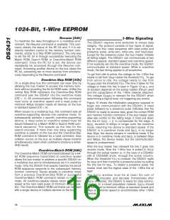
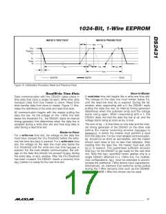
Figure 10. Initialization Procedure: Reset and Presence Pulse
Slave-to-Master
Read/Write Time Slots
Data communication with the DS2431 takes place in
time slots that carry a single bit each. Write time slots
transport data from bus master to slave. Read time
slots transfer data from slave to master. Figure 11 illus-
trates the definitions of the write and read time slots.
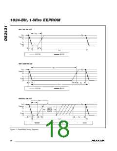
A read-data time slot begins like a write-one time slot.
The voltage on the data line must remain below V
TL
until the read low time t
is expired. During the t
RL
RL
window, when responding with a 0, the DS2431 starts
pulling the data line low; its internal timing generator
determines when this pulldown ends and the voltage
starts rising again. When responding with a 1, the
DS2431 does not hold the data line low at all, and the
All communication begins with the master pulling the
data line low. As the voltage on the 1-Wire line falls
below the threshold V , the DS2431 starts its internal
TL
timing generator that determines when the data line is
sampled during a write time slot and how long data is
valid during a read time slot.
voltage starts rising as soon as t is over.
RL
The sum of t + δ (rise time) on one side and the inter-
nal timing generator of the DS2431 on the other side
RL
define the master sampling window (t
to
MSRMIN
Master-to-Slave
t
), in which the master must perform a read
MSRMAX
For a write-one time slot, the voltage on the data line
from the data line. For the most reliable communication,
should be as short as permissible, and the master
must have crossed the V threshold before the write-
TH
t
RL
one low time t
is expired. For a write-zero time
W1LMAX
should read close to but no later than t
. After
MSRMAX
slot, the voltage on the data line must stay below the
threshold until the write-zero low time t is
reading from the data line, the master must wait until
is expired. This guarantees sufficient recovery
V
TH
W0LMIN
t
SLOT
time t
expired. For the most reliable communication, the volt-
age on the data line should not exceed V during
for the DS2431 to get ready for the next time
REC
ILMAX
slot. Note that t
specified herein applies only to a
REC
the entire t
or t
window. After the V threshold
W1L TH
W0L
single DS2431 attached to a 1-Wire line. For multide-
vice configurations, t must be extended to accom-
has been crossed, the DS2431 needs a recovery time
before it is ready for the next time slot.
REC
t
REC
modate the additional 1-Wire device input capacitance.
Alternatively, an interface that performs active pullup
during the 1-Wire recovery time such as the DS2482-
x00 or DS2480B 1-Wire line drivers can be used.
______________________________________________________________________________________ 17

 MAXIM [ MAXIM INTEGRATED PRODUCTS ]