DS2413: 1-Wire Dual Channel Addressable Switch
Read/Write Time Slots
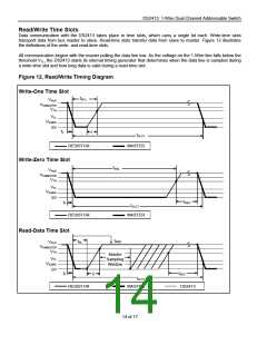
Data communication with the DS2413 takes place in time slots, which carry a single bit each. Write-time slots
transport data from bus master to slave. Read-time slots transfer data from slave to master. Figure 12 illustrates
the definitions of the write- and read-time slots.
All communication begins with the master pulling the data line low. As the voltage on the 1-Wire line falls below the
threshold VTL, the DS2413 starts its internal timing generator that determines when the data line is sampled during
a write-time slot and how long data is valid during a read-time slot.
Figure 12. Read/Write Timing Diagram
Write-One Time Slot
tW1L
VPUP
VIHMASTER
VTH
VTL
VILMAX
0V
tF
ꢀ
tSLOT
RESISTOR
MASTER
Write-Zero Time Slot
tW0L
VPUP
VIHMASTER
VTH
VTL
VILMAX
0V
tREC
tF
tSLOT
RESISTOR
MASTER
Read-Data Time Slot
tMSR
tRL
VPUP
VIHMASTER
VTH
Master
Sampling
Window
VTL
VILMAX
0V
tF
tREC
DS2413
ꢀ
tSLOT
RESISTOR
MASTER
14 of 17

 MAXIM [ MAXIM INTEGRATED PRODUCTS ]