DS1624
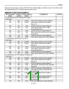
PAGE PROGRAM MODE
To program the DS1624 the master sends addresses and data to the DS1624 which is the slave. This is
done by supplying a START condition followed by the 4–bit device code, the 3–bit slave address, and the
R/
W
bit which is defined as a logic LOW for a write. The master then sends the Access Memory
protocol. This indicates to the addressed slave that a word address will follow. The slave outputs the
acknowledge pulse to the master during the ninth clock pulse. When the word address is received by the
DS1624 it is placed in the address pointer defining which memory location is to be written. The DS1624
will generate an acknowledge after every 8–bits received and store them consecutively in an 8–byte RAM
until a STOP condition is detected which initiates the internal programming cycle.
A repeated START condition, instead of a STOP condition, will abort the programming operation.
During the programming cycle the DS1624 will not acknowledge any further accesses to the device until
the programming cycle is complete (approximately 10 ms).
If more than 8 bytes are transmitted by the master the DS1624 will roll over and overwrite the data
beginning with the first received byte. This does not affect erase/ write cycles of the EEPROM array and
is accomplished as a result of only allowing the address register’s bottom 3 bits to increment while the
upper 5 bits remain unchanged. The DS1624 is capable of 50,000 writes (25,000 erase/write cycles)
before EEPROM wear out may occur.
If the master generates a STOP condition after transmitting the first data word, byte programming mode
is entered.
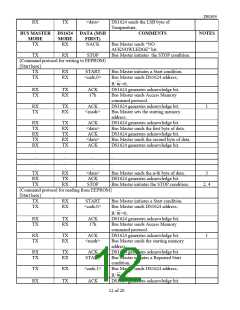
READ MODE
In this mode, the master is reading data from the DS1624 E2 memory. The master first provides the slave
address to the device with R/
W
set to “0”. The master then sends the Access Memory protocol and, after
receiving an acknowledge, then provides the word address, which is the address of the memory location
at which it wishes to begin reading. Note that while this is a read operation the address pointer must first
be written. During this period the DS1624 generates acknowledge bits as defined in the appropriate
section.
The master now generates another START condition and transmits the slave address. This time the R/
W
bit is set to “1” to put the DS1624 in read mode. After the DS1624 generates the acknowledge bit it
outputs the data from the addressed location on the SDA pin, increments the address pointer, and, if it
receives an acknowledge from the master, transmits the next consecutive byte. This auto-increment
sequence is only aborted when the master sends a STOP condition instead of an acknowledge. When the
address pointer reaches the end of the 256–byte memory space (address FFh) it will increment from the
end of the memory back to the first location of the memory (address 00h).
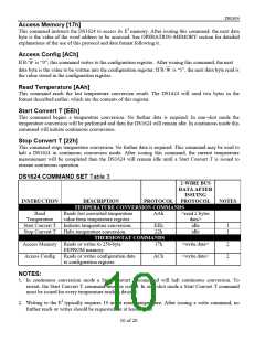
COMMAND SET
Data and control information is read from and written to the DS1624 in the format shown in Figure 3. To
write to the DS1624, the master will issue the slave address of the DS1624 and the R/
W
bit will be set to
“0”. After receiving an acknowledge the bus master provides a command protocol. After receiving this
protocol the DS1624 will issue an acknowledge then the master may send data to the DS1624. If the
DS1624 is to be read, the master must send the command protocol as before then issue a repeated START
condition and the control byte again, this time with the R/
W
bit set to “1” to allow reading of the data
from the DS1624. The command set for the DS1624 as shown in Table 3 is as follows:
9 of 20

 MAXIM [ MAXIM INTEGRATED PRODUCTS ]