DS1624
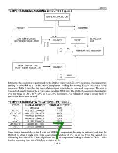
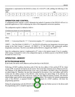
Temperature is represented in the DS1624 in terms of a 0.03125°C LSB, yielding the following 13–bit
format:
MSB
LSB
0
0
0
0
1
1
0
0
1
0
0
0
1
0
0
0
= +25.0625°C
OPERATION AND CONTROL
A configuration/status register is used to determine the method of operation of the DS1624 will use in a
particular application as well as indicating the status of the temperature conversion operation.
The configuration register is defined as follows:
CONFIGURATION/STATUS REGISTER
DONE
1
0
0
1
0
1
1SHOT
where
DONE = Conversion Done bit. “1” = Conversion complete, “0” = conversion in progress.
1SHOT = One Shot Mode. If 1SHOT is “1”, the DS1624 will perform one temperature conversion upon
receipt of the Start Convert T protocol. If 1SHOT is “0”, the DS1624 will continuously perform
temperature conversions. This bit is nonvolatile and the DS1624 is shipped with 1SHOT = “0”.
Since the configuration register is implemented in E2, writes to the register require 10 ms to complete.
After issuing a command to write to the configuration register, no further accesses to the DS1624 should
be made for at least 10 ms.
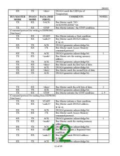
OPERATION – MEMORY
BYTE PROGRAM MODE
In this mode, the master sends addresses and one data byte to the DS1624.
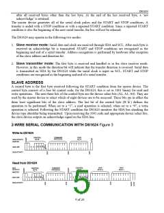
Following a START condition, the device code (4–bit), the slave address (3 bit), and the R/
W
bit, which
is logic LOW, are placed onto the bus by the master. The master then sends the Access Memory protocol.
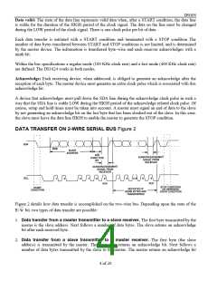
This indicates to the addressed DS1624 that a byte with a word address will follow after it has generated
an acknowledge bit. Therefore, the next byte transmitted by the master is the word address and will be
written into the address pointer of the DS1624. After receiving the acknowledge of the DS1624, the
master device transmits the data word to be written into the addressed memory location. The DS1624
acknowledges again and the master generates a STOP condition. This initiates the internal programming
cycle of the DS1624. A repeated START condition, instead of a STOP condition, will abort the
programming operation.
During the programming cycle the DS1624 will not acknowledge any further accesses to the device until
the programming cycle is complete (approximately 10 ms.)
8 of 20

 MAXIM [ MAXIM INTEGRATED PRODUCTS ]