DS1624
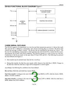
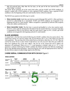
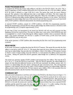
DS1624 FUNCTIONAL BLOCK DIAGRAM Figure 1
STATUS REGISTER &
VDD
CONTROL LOGIC
SCL
SDA
TEMPERATURE SENSOR
ADDRESS
AND
I/O CONTROL
EEPROM MEMORY (256 BYTES)
A0
A1
A2
GND
2-WIRE SERIAL DATA BUS
The DS1624 supports a bi–directional two–wire bus and data transmission protocol. A device that sends
data onto the bus is defined as a transmitter, and a device receiving data as a receiver. The device that
controls the message is called a “master”. The devices that are controlled by the master are “slaves”. The
bus must be controlled by a master device which generates the serial clock (SCL), controls the bus access,
and generates the START and STOP conditions. The DS1624 operates as a slave on the two–wire bus.
Connections to the bus are made via the open–drain I/O lines SDA and SCL. The following bus protocol
has been defined (See Figure 2):
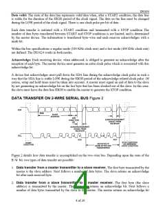
• Data transfer may be initiated only when the bus is not busy.
• During data transfer, the data line must remain stable whenever the clock line is HIGH. Changes in
the data line while the clock line is high will be interpreted as control signals.
Accordingly, the following bus conditions have been defined:
Bus not busy: Both data and clock lines remain HIGH.
Start data transfer: A change in the state of the data line, from HIGH to LOW, while the clock is HIGH,
defines a START condition.
Stop data transfer: A change in the state of the data line, from LOW to HIGH, while the clock line is
HIGH, defines the STOP condition.
3 of 20

 MAXIM [ MAXIM INTEGRATED PRODUCTS ]