LTC3101
ABSOLUTE MAXIMUM RATINGS
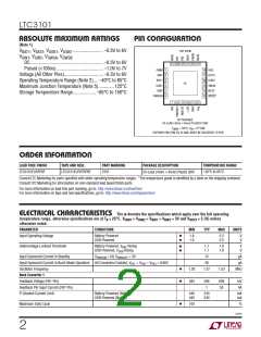
PIN CONFIGURATION
(Note 1)
V
V
, V
, V
, V
......................... –0.3V to 6V
TOP VIEW
BAT1 BAT2 USB1 USB2
, V
, V
, V
SW1 SW2 SW3A SW3B
DC............................................................ –0.3V to 6V
Pulsed (<100ns) ...................................... –1.0V to 7V
24 23 22 21 20 19
PWM
SW1
1
2
3
4
5
6
18 HSO
Voltage (All Other Pins)................................ –0.3V to 6V
Operating Temperature Range (Note 2).... –40°C to 85°C
Maximum Junction Temperature (Note 5)............. 125°C
Storage Temperature Range................... –65°C to 150°C
OUT3
USB2
17
16
BAT1
25
USB1
SW2
15 SW3A
14 BAT2
13 RESET
PWRON
7
8
9 10 11 12
UF PACKAGE
24-LEAD (4mm s 4mm) PLASTIC QFN
T
JMAX
= 125°C, θ = 37°C/W
JA
EXPOSED PAD (PIN 25) IS GND, MUST BE SOLDERED TO PCB
ORDER INFORMATION
LEAD FREE FINISH
TAPE AND REEL
PART MARKING
PACKAGE DESCRIPTION
24-Lead (4mm × 4mm) Plastic QFN
TEMPERATURE RANGE
–40°C to 85°C
LTC3101EUF#PBF
LTC3101EUF#TRPBF
3101
Consult LTC Marketing for parts specified with wider operating temperature ranges. *The temperature grade is identified by a label on the shipping container.
Consult LTC Marketing for information on non-standard lead based finish parts.
For more information on lead free part marking, go to: http://www.linear.com/leadfree/
For more information on tape and reel specifications, go to: http://www.linear.com/tapeandreel/
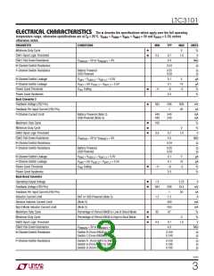
ELECTRICAL CHARACTERISTICS The l denotes the specifications which apply over the full operating
temperature range, otherwise specifications are at TA = 25°C. VUSB1 = VUSB2 = VBAT1 = VBAT2 = 3V and VOUT3 = 3.3V, unless
otherwise noted.
PARAMETER
CONDITIONS
MIN
TYP
MAX
UNITS
l
l
Input Operating Voltage
Battery Powered
USB Powered
1.8
1.8
5.5
5.5
V
V
l
l
Undervoltage Lockout Threshold
Battery Powered, V Rising
1.7
1.7
1.8
1.8
V
V
BAT
USB Powered, V
Rising
USB
Input Quiescent Current in Standby
V
= 0V, V
= 3V
PWRKEY
15
38
μA
μA
PWRON
Input Quiescent Current in Burst Mode Operation All Converters Enabled, V
Oscillator Frequency
= V
= V
= 0.66V
FB1
FB2
FB3
l
l
1.02
583
1.27
1.52
MHz
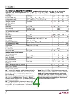
Buck Converter 1
Feedback Voltage (FB1 Pin)
596
1
609
50
mV
nA
Feedback Pin Input Current (FB1 Pin)
P-Channel Current Limit
Battery Powered (Note 3)
USB Powered (Note 3)
440
440
540
540
mA
mA
l
Maximum Duty Cycle
100
%
3101f
2

 Linear [ Linear ]