LT8705
ORDER INFORMATION
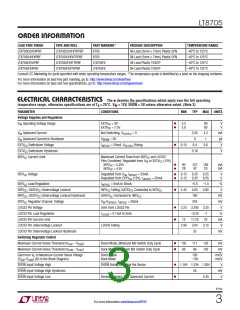
LEAD FREE FINISH
LT8705EUHF#PBF
LT8705IUHF#PBF
LT8705EFE#PBF
LT8705IFE#PBF
TAPE AND REEL
PART MARKING*
8705
PACKAGE DESCRIPTION
TEMPERATURE RANGE
–40°C to 125°C
–40°C to 125°C
–40°C to 125°C
–40°C to 125°C
LT8705EUHF#TRPBF
LT8705IUHF#TRPBF
LT8705EFE#TRPBF
LT8705IFE#TRPBF
38-Lead (5mm × 7mm) Plastic QFN
38-Lead (5mm × 7mm) Plastic QFN
38-Lead Plastic TSSOP
8705
LT8705FE
LT8705FE
38-Lead Plastic TSSOP
Consult LTC Marketing for parts specified with wider operating temperature ranges. *The temperature grade is identified by a label on the shipping container.
For more information on lead free part marking, go to: http://www.linear.com/leadfree/
For more information on tape and reel specifications, go to: http://www.linear.com/tapeandreel/
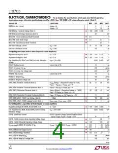
ELECTRICAL CHARACTERISTICS The l denotes the specifications which apply over the full operating
temperature range, otherwise specifications are at TA = 25°C. VIN = 12V, SHDN = 3V unless otherwise noted. (Note 3)
PARAMETER
CONDITIONS
MIN
TYP
MAX UNITS
Voltage Supplies and Regulators
l
l
V
Operating Voltage Range
EXTV = 0V
5.5
2.8
80
80
V
V
IN
CC
EXTV = 7.5V
CC
V
V
Quiescent Current
Not Switching, V
= 0
2.65
0
4.2
1
mA
µA
V
IN
EXTVCC
Quiescent Current in Shutdown
V
SHDN
= 0V
IN
l
EXTV Switchover Voltage
I
= 20mA, V Rising
EXTVCC
6.15
6.4
0.18
6.6
CC
INTVCC
EXTV Switchover Hysteresis
V
CC
INTV Current Limit
Maximum Current Draw from INTV and LDO33
CC
CC
Pins Combined. Regulated from V or EXTV (12V)
IN
CC
l
l
INTV = 5.25V
90
28
127
42
165
55
mA
mA
CC
INTV = 4.5V
CC
l
l
INTV Voltage
Regulated from V , I
= 20mA
6.15
6.15
6.35
6.35
6.55
6.55
V
V
CC
IN INTVCC
Regulated from EXTV (12V), I
= 20mA
CC
INTVCC
INTV Load Regulation
I
= 0mA to 50mA
INTVCC
–0.5
4.65
160
245
–1.5
4.85
%
V
CC
l
INTV , GATEV Undervoltage Lockout
INTV Falling, GATEV Connected to INTV
CC
4.45
CC
CC
CC
CC
INTV , GATEV Undervoltage Lockout Hysteresis
GATEV Connected to INTV
CC
mV
mV
V
CC
CC
CC
INTV Regulator Dropout Voltage
V -V
, I
= 20mA
CC
IN INTVCC INTVCC
l
l
LDO33 Pin Voltage
5mA from LDO33 Pin
= 0.1mA to 5mA
3.23 3.295 3.35
LDO33 Pin Load Regulation
LDO33 Pin Current Limit
I
–0.25
17.25
3.04
35
–1
22
%
LDO33
12
mA
V
LDO33 Pin Undervoltage Lockout
LDO33 Pin Undervoltage Lockout Hysteresis
Switching Regulator Control
LDO33 Falling
2.96
3.12
mV
l
l
Maximum Current Sense Threshold (V
Maximum Current Sense Threshold (V
– V
)
)
Boost Mode, Minimum M3 Switch Duty Cycle
Buck Mode, Minimum M2 Switch Duty Cycle
102
69
117
86
132
102
mV
mV
CSP
CSN
CSN
– V
CSP
Gain from V to Maximum Current Sense Voltage
CSP CSN
Boost Mode
Buck Mode
150
–150
mV/V
mV/V
C
(V -V ) (A5 in the Block Diagram)
l
l
SHDN Input Voltage High
SHDN Rising to Enable the Device
1.184 1.234 1.284
V
mV
V
SHDN Input Voltage High Hysteresis
SHDN Input Voltage Low
50
Device Disabled, Low Quiescent Current
0.35
8705p
3
For more information www.linear.com/8705

 Linear [ Linear ]