LT3518
APPLICATIONS INFORMATION
Switching Frequency
to generate a switching frequency 20% lower than the
external clock when external clock is absent.
There are two methods to set the switching frequency of
LT3518. Both methods require a resistor connected at R
In general, a lower switching frequency should be used
where either very high or very low switching duty cycle
operationisrequired,orhighefficiencyisdesired.Selection
of a higher switching frequency will allow use of smaller
value external components and yield a smaller solution
size and profile.
T
pin. Do not leave the R pin open. Also, do not load this pin
T
with a capacitor. A resistor must always be connected for
proper operation. One way to set the frequency is simply
connectinganexternalresistorbetweentheR pinandGND.
T
See Table 4 below or see the Oscillator Frequency vs R
T
graphintheTypicalPerformanceCharacteristicsforresis-
Thermal Considerations
tor values and corresponding switching frequencies.
The LT3518 is rated to a maximum input voltage of 30V
for continuous operation, and 40V for nonrepetitive one
second transients. Careful attention must be paid to the
internal power dissipation of the LT3518 at higher input
voltagestoensurethatthemaximumjunctiontemperature
is not exceeded. This junction limit is especially important
whenoperatingathighambienttemperatures.TheExposed
Pad on the bottom of the package must be soldered to a
ground plane. This ground should then be connected to
an internal copper ground plane with thermal vias placed
directlyunderthepackagetospreadouttheheatdissipated
by the LT3518.
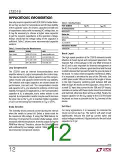
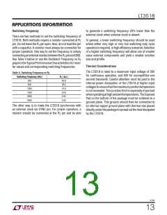
Table 4. Switching Frequency vs RT
Switching Frequency (kHz)
R ( kΩ )
T
250
500
90.9
39.2
16.9
9.53
6.04
4.02
1000
1500
2000
2500
The other way is to make the LT3518 synchronize with
an external clock via SYNC pin. For proper operation, a
resistor should be connected at the R pin and be able
T
3518fb
13

 Linear [ Linear ]