LT3518
APPLICATIONS INFORMATION
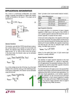
For a buck or a buck-boost configuration, the output
voltage is typically level-shifted to a signal with respect
to GND as illustrated in the Figure 4. The output can be
expressed as:
Table 1 provides some recommended inductor vendors.
Table 1. Inductor Manufacturers
VENDOR
Sumida
Toko
PHONE
WEB
(408) 321-9660
(408) 432-8281
(561) 998-4100
(402) 563-6866
www.sumida.com
www.toko.com
www.cooperet.com
www.vishay.com
R1
VOUT
=
•1.01V + VBE(Q1)
(5)
Cooper
Vishay
R2
+
R1
R
SENSE
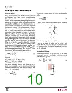
Input Capacitor Selection
V
OUT
LED
ARRAY
For proper operation, it is necessary to place a bypass
–
LT3518
FB
capacitor to GND close to the V pin of the LT3518. A
IN
1μF or greater capacitor with low ESR should be used. A
R2
ceramic capacitor is usually the best choice.
3518 F04
In the buck mode configuration, the capacitor at the input
to the power converter has large pulsed currents due to
the current returned though the Schottky diode when the
switchisoff. Forbestreliability, thiscapacitorshouldhave
low ESR and ESL and have an adequate ripple current
rating. The RMS input current is:
Figure 4
Inductor Selection
The inductor used with the LT3518 should have a satura-
tion current rating of 2A or greater. For buck mode LED
drivers, the inductor value should be chosen to give a
ripple current “ΔI” of ~30% to 40% of the LED current.
In the buck mode, the inductor value can be estimated
using the formula:
IIN(RMS) =ILED • (1–D)•D
(8)
where D is the switch duty cycle. A 2.2μF ceramic type
capacitor is usually sufficient.
D
BUCK • tSW(µs) • V – V
(
)
Output Capacitor Selection
IN LED
L µH =
(
)
(6)
ꢀI
The selection of output capacitor depends on the load
and converter configuration, i.e., step-up or step-down.
For LED applications, the equivalent resistance of the LED
is typically low, and the output filter capacitor should be
sized to attenuate the current ripple.
VLED
V
DBUCK
=
IN
V
is the voltage across the LED string, V is the input
IN
LED
voltage to the converter, and t is the switching period.
ToachievethesameLEDripplecurrent, therequiredfilter
capacitorvalueislargerintheboostandbuck-boostmode
applications than that in the buck mode applications. For
LED buck mode applications, a 1μF ceramic capacitor
is usually sufficient. For the LED boost and buck-boost
mode applications, a 2.2μF ceramic capacitor is usually
sufficient. Very high performance PWM dimming appli-
cations may require a larger capacitor value to support
the LED voltage during PWM transitions.
SW
In the boost configuration, the inductor can be estimated
using the formula:
DBOOST • tSW(µs) • V
IN
L µH =
(
)
(7)
ꢀI
VLED – V
IN
DBOOST
=
VLED
3518fb
11

 Linear [ Linear ]