LT3518
APPLICATIONS INFORMATION
Dimming Control
When V
to be:
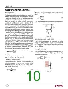
is higher than 1V, the LED current is clamped
(3)
CTRL
There are two methods to control the current source for
dimming using the LT3518. The first method uses the
PWM pin to modulate the current source between zero
and full current to achieve a precisely programmed aver-
age current. To make this method of current control more
100mV
ILED
=
RSENSE
The LED current programming feature possibly increases
accurate, the switch demand current is stored on the V
C
2V
node during the quiescent phase. This feature minimizes
recovery time when the PWM signal goes high. To further
improve the recovery time, a disconnect switch is used in
the LED current path to prevent the output capacitor from
discharging in the PWM signal low phase. The minimum
PWM on or off time will depend on the choice of operating
V
REF
45.3k
49.9k
CTRL
5k
PTC
3518 F02
frequency through R input pin or SYNC pin. When using
T
the SYNC function, the SYNC and PWM signals must have
thealignedrisingedgestoachievetheoptimizedhighPWM
dimming ratio. For best current accuracy, the minimum
PWM low or high time should be at least six switching
Figure 2
total dimming range by a factor of ten.
The CTRL pin should not be left open (tie to V
if not
REF
cycles (3μs for f = 2MHz). Maximum PWM period is
SW
used). The CTRL pin can also be used in conjunction with
a PTC thermistor to provide overtemperature protection
for the LED load.
determined by the system and is unlikely to be longer than
12ms.ThemaximumPWMdimmingratio(PWM
)can
) and
RATIO
be calculated from the maximum PWM period (t
MAX
the minimum PWM pulse width (t ) as follows:
MIN
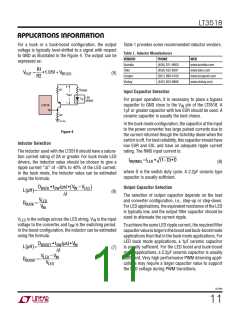
Setting Output Voltage
tMAX
tMIN
For a boost application, the output voltage can be set by
selecting the values of R1 and R2 (see Figure 3) according
to the following equation:
PWMRATIO
=
(1)
Example:
= 9ms, t
R1
R2
ꢀ
ꢁ
ꢃ
ꢄ
t
= 3μs (f = 2MHz)
SW
MAX
MIN
VOUT
=
+1 •1.01V
(4)
ꢂ
ꢅ
PWM
= 9ms/3μs = 3000:1
RATIO
The second method of dimming control uses the CTRL
pin to linearly adjust the current sense threshold during
the PWM high state. When the CTRL pin voltage is less
than 1V, the LED current is:
V
OUT
R1
LT3518
FB
R2
3518 F03
VCTRL
10 •RSENSE
ILED
=
(2)
Figure 3
3518fb
10

 Linear [ Linear ]