LTC3703
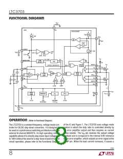
operaTion (Refer to Functional Diagram)
For maximum protection, the LTC3703 current limit con-
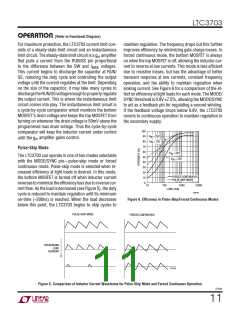
maintain regulation. The frequency drops but this further
improves efficiency by minimizing gate charge losses. In
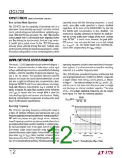
forced continuous mode, the bottom MOSFET is always
on when the top MOSFET is off, allowing the inductor cur-
rent to reverse at low currents. This mode is less efficient
due to resistive losses, but has the advantage of better
transient response at low currents, constant frequency
operation, and the ability to maintain regulation when
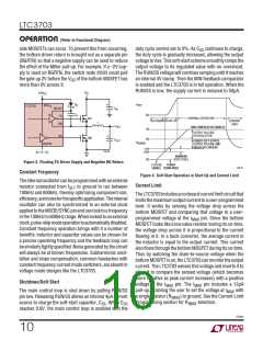
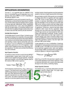
sinking current. See Figure 6 for a comparison of the ef-
fect on efficiency at light loads for each mode. The MODE/
SYNC threshold is 0.8V 7.5%, allowing the MODE/SYNC
to act as a feedback pin for regulating a second winding.
If the feedback voltage drops below 0.8V, the LTC3703
reverts to continuous operation to maintain regulation in
the secondary supply.
sists of a steady-state limit circuit and an instantaneous
limit circuit. The steady-state limit circuit is a g amplifier
m
that pulls a current from the RUN/SS pin proportional
to the difference between the SW and I
voltages.
MAX
This current begins to discharge the capacitor at RUN/
SS, reducing the duty cycle and controlling the output
voltage until the current regulates at the limit. Depending
on the size of the capacitor, it may take many cycles to
dischargetheRUN/SSvoltageenoughtoproperlyregulate
the output current. This is where the instantaneous limit
circuit comes into play. The instantaneous limit circuit is
a cycle-by-cycle comparator which monitors the bottom
MOSFET’s drain voltage and keeps the top MOSFET from
turning on whenever the drain voltage is 50mV above the
programmed max drain voltage. Thus the cycle-by-cycle
comparator will keep the inductor current under control
100
V
= 25V
= 75V
90
80
70
60
50
40
30
20
10
0
IN
until the g amplifier gains control.
m
V
IN
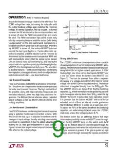
Pulse-Skip Mode
V
= 25V
IN
The LTC3703 can operate in one of two modes selectable
with the MODE/SYNC pin—pulse-skip mode or forced
continuous mode. Pulse-skip mode is selected when in-
creased efficiency at light loads is desired. In this mode,
the bottom MOSFET is turned off when inductor current
reversestominimizetheefficiencylossduetoreversecur-
rent flow. As the load is decreased (see Figure 5), the duty
cycle is reduced to maintain regulation until its minimum
on-time (~200ns) is reached. When the load decreases
below this point, the LTC3703 begins to skip cycles to
V
= 75V
IN
FORCED CONTINUOUS
PULSE SKIP MODE
10
100
1000
10000
LOAD (mA)
3703 F06
Figure 6. Efficiency in Pulse-Skip/Forced Continuous Modes
PULSE-SKIP MODE
FORCED CONTINUOUS
DECREASING
LOAD
CURRENT
3703 F05
Figure 5. Comparison of Inductor Current Waveforms for Pulse-Skip Mode and Forced Continuous Operation
3703fc
11

 Linear Systems [ Linear Systems ]