LTC3703
operaTion (Refer to Functional Diagram)
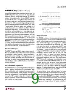
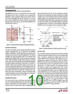
side MOSFETs can occur. To prevent this from occurring,
the bottom driver return is brought out as a separate pin
(BGRTN) so that a negative supply can be used to reduce
the effect of the Miller pull-up. For example, if a –2V sup-
ply is used on BGRTN, the switch node dV/dt could pull
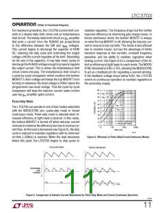
duty cycle control set to 0%. As C continues to charge,
SS
the duty cycle is gradually increased, allowing the output
voltagetorise.Thissoft-startschemesmoothlyrampsthe
output voltage to its regulated value with no overshoot.
The RUN/SS voltage will continue ramping until it reaches
an internal 4V clamp. Then the MIN feedback comparator
is enabled and the LTC3703 is in full operation. When the
RUN/SS is low, the supply current is reduced to 50µA.
the gate up 2V before the V of the bottom MOSFET has
GS
more than 0V across it.
V
DRV
IN
CC
V
OUT
D
+
B
DRV
LTC3703
CC
BOOST
TG
C
IN
C
0V
B
NORMAL OPERATION
MT
SHUTDOWN START-UP
CURRENT
LIMIT
L
SW
V
OUT
MIN COMPARATOR ENABLED
4V
3V
OUTPUT VOLTAGE
IN REGULATION
BG
+
MB
C
OUT
RUN/SS SOFT-STARTS
OUTPUT VOLTAGE AND
INDUCTOR CURRENT
V
RUN/SS
BGRTN
0V TO –5V
1.4V
0.9V
3703 F03
MINIMUM
DUTY CYCLE
0V
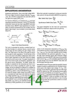
Figure 3. Floating TG Driver Supply and Negative BG Return
LTC3703
POWER
ENABLE DOWN MODE
3703 F04
Constant Frequency
Figure 4. Soft-Start Operation in Start-Up and Current Limit
Theinternaloscillatorcanbeprogrammedwithanexternal
Current Limit
resistor connected from f
to ground to run between
SET
100kHz and 600kHz, thereby optimizing component size,
efficiency,andnoiseforthespecificapplication.Theinternal
oscillator can also be synchronized to an external clock
appliedtotheMODE/SYNCpinandcanlocktoafrequency
inthe100kHzto600kHzrange.Whenlockedtoanexternal
clock,pulse-skipmodeoperationisautomaticallydisabled.
Constant frequency operation brings with it a number of
benefits: inductor and capacitor values can be chosen for
a precise operating frequency and the feedback loop can
besimilarlytightlyspecified.Noisegeneratedbythecircuit
will always be at known frequencies. Subharmonic oscil-
lation and slope compensation, common headaches with
constant frequency current mode switchers, are absent in
voltage mode designs like the LTC3703.
TheLTC3703includesanonboardcurrentlimitcircuitthat
limitsthemaximumoutputcurrenttoauser-programmed
level. It works by sensing the voltage drop across the
bottom MOSFET and comparing that voltage to a user-
programmed voltage at the I
pin. Since the bottom
MAX
MOSFET looks like a low value resistor during its on-time,
the voltage drop across it is proportional to the current
flowing in it. In a buck converter, the average current in
the inductor is equal to the output current. This current
alsoflowsthroughthebottomMOSFETduringitson-time.
Thus by watching the drain-to-source voltage when the
bottomMOSFETison,theLTC3703canmonitortheoutput
current. The LTC3703 senses this voltage and inverts it to
allow it to compare the sensed voltage (which becomes
more negative as peak current increases) with a positive
Shutdown/Soft-Start
voltage at the I
pin. The I
pin includes a 12µA
MAX
MAX
pull-up, enabling the user to set the voltage at I
with
The main control loop is shut down by pulling RUN/SS
pin low. Releasing RUN/SS allows an internal 4µA current
source to charge the soft-start capacitor, C . When C
MAX
a single resistor (R
) to ground. See the Current Limit
IMAX
Programming section for R
selection.
IMAX
SS
SS
reaches 0.9V, the main control loop is enabled with the
3703fc
10

 Linear Systems [ Linear Systems ]