LTC4060
U
TYPICAL APPLICATIO S
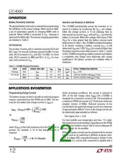
Trickle Charge
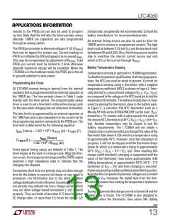
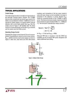
resistance and mismatches in the two sense resistor’s
value will cause charge current variability to increase in
proportion to the extension in current. Resistor RISET
should be connected directly to the LTC4060 to reduce
errors.Thetotalcurrentsenseresistor,bondwireandlead
frameresistanceisapproximately0.08Ω(T.C.≅3500ppm/
°C). The formula for extended fast charge current is:
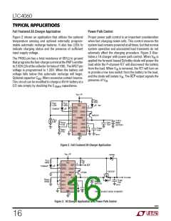
The trickle charge function is normally not required due to
the automatic recharge feature. However, the LTC4060
does provide a modest pull-up current (IBRD) as part of its
battery removal detection method. If additional current is
required for trickle charge or to support battery removal
detection with current loads greater than IBRD, then the
simple circuit of Figure 4 will facilitate that. The diode
insuresnoreversedischargecurrentwhenVIN isremoved
and the resistor sets the trickle current.
⎛
0.08 ⎞
I
MAX(EXT) = IMAX • 1+
⎜
⎟
⎝
RISET
⎠
= 2A •1.5 = 3A
Extending Charge Current
for RISET = 0.16Ω and RPROG = 698Ω.
Extending the charge current beyond 2A can be accom-
plished by paralleling an external current sense resistor,
Adequate PNP beta is required to meet the DRIVE pin
capability and the increased PNP power dissipation will
require additional heat sinking.
R
ISET, with the internal current sense resistor as shown in
Figure 5. Bond wire, lead frame and PCB interconnect
V
1N4001
IN
14
V
CC
LTC4060
SENSE
3.3k
3
1
2
DRIVE
BAT
+
2-CELL
NiMH
BATTERY
4060 F04
Figure 4. Adding Trickle Charge
V
IN
14
R
ISET
0.16Ω
V
CC
0.08Ω
3
SENSE
DRIVE
BAT
1
2
+
2-CELL
NiMH
LTC4060
BATTERY
4060 F05
Figure 5. Extended Charge Current Operation
4060f
17

 Linear Systems [ Linear Systems ]