Data Sheet
ESTW010A0A Series Eighth-Brick Power Modules
November 29, 2011
36–75Vdc Input; 5.0Vdc Output; 10A Output Current
the module remains at or below the maximum rated
power (Maximum rated power = Vo,set x Io,max).
Feature Description
Remote On/Off
Two remote on/off options are available. Positive logic
turns the module on during a logic high voltage on the
ON/OFF pin, and off during a logic low. Negative logic
remote On/Off, device code suffix “1”, turns the
module off during a logic high and on during a logic
low.
SENSE(+)
SENSE(–)
VI(+)
VI(-)
VO(+)
IO
SUPPLY
LOAD
II
VO(–)
CONTACT
RESISTANCE
CONTACT AND
DISTRIBUTION LOSSES
Vin+
Vout+
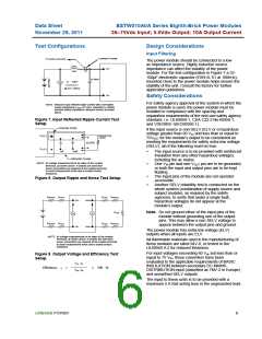
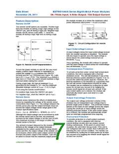
Figure 11. Circuit Configuration for remote
sense .
Ion/off
ON/OFF
TRIM
Input Undervoltage Lockout
At input voltages below the input undervoltage lockout
limit, the module operation is disabled. The module
will only begin to operate once the input voltage is
raised above the undervoltage lockout turn-on
Von/off
Vout-
Vin-
threshold, VUV/ON
.
Once operating, the module will continue to operate
until the input voltage is taken below the undervoltage
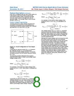
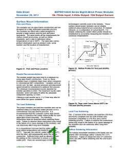
Figure 10. Remote On/Off Implementation.
turn-off threshold, VUV/OFF
.
Overtemperature Protection
To turn the power module on and off, the user must
supply a switch (open collector or equivalent) to
control the voltage (Von/off) between the ON/OFF
terminal and the VIN(-) terminal (see Figure 10). Logic
low is 0V ≤ Von/off ≤ 0.6V. The maximum Ion/off during a
logic low is 0.15mA; the switch should maintain a logic
low level whilst sinking this current.
To provide protection under certain fault temperature
conditions, the unit is equipped with a thermal
shutdown circuit. The unit will shutdown if any of the
thermal reference points identified in Figures 13 & 14,
exceed the stated trip points (typical). However, the
thermal shutdown is not intended as a guarantee that
the unit will survive temperatures beyond its rating.
The module can be restarted by cycling the dc input
power for at least one second or by toggling the
remote on/off signal for at least one second. If the
auto-restart option (4) is ordered, the module will
automatically restart upon cool-down to a safe
temperature.
During a logic high, the typical maximum Von/off
generated by the module is 15V, and the maximum
allowable leakage current at Von/off = 2.4V is 25μA.
If not using the remote on/off feature:
For positive logic, leave the ON/OFF pin open.
For negative logic, short the ON/OFF pin to VIN(-).
Remote Sense
Output Overvoltage Protection
Remote sense minimizes the effects of distribution
losses by regulating the voltage at the remote-sense
connections (See Figure 11). The voltage between the
remote-sense pins and the output terminals must not
exceed the output voltage sense range given in the
Feature Specifications table:
The output over voltage protection scheme of the
modules has an independent over voltage loop to
prevent single point of failure. This protection feature
latches in the event of over voltage across the output.
Cycling the on/off pin or input voltage resets the
latching protection feature. If the auto-restart option
(4) is ordered, the module will automatically restart
upon an internally programmed time elapsing.
[VO(+) – VO(–)] – [SENSE(+) – SENSE(–)] 0.5 V
Although the output voltage can be increased by both
the remote sense and by the trim, the maximum
increase for the output voltage is not the sum of both.
The maximum increase is the larger of either the
remote sense or the trim.
Overcurrent Protection
To provide protection in a fault (output overload)
condition, the unit is equipped with internal
current-limiting circuitry and can endure current
limiting continuously. At the point of current-limit
inception, the unit enters hiccup mode. If the unit is
not configured with auto–restart, then it will latch off
following the over current condition. The module can
be restarted by cycling the dc input power for at least
one second or by toggling the remote on/off signal for
at least one second.
The amount of power delivered by the module is
defined as the voltage at the output terminals
multiplied by the output current. When using remote
sense and trim, the output voltage of the module can
be increased, which at the same output current would
increase the power output of the module. Care should
be taken to ensure that the maximum output power of
LINEAGE POWER
7

 LINEAGEPOWER [ LINEAGE POWER CORPORATION ]