Specifications GAL20V8Z
GAL20V8ZD
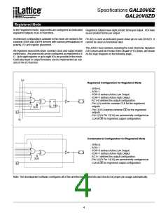
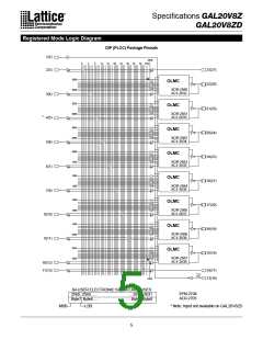
Registered Mode
In the Registered mode, macrocells are configured as dedicated
registered outputs or as I/O functions.
Registered outputs have eight product terms per output. I/Os have
seven product terms per output.
Architecture configurations available in this mode are similar to the
common 20R8 and 20RP4 devices with various permutations of
polarity, I/O and register placement.
Pin 4(5) is used as dedicated power-down pin on GAL20V8ZD. It
cannot be used as functional input.
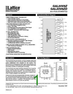
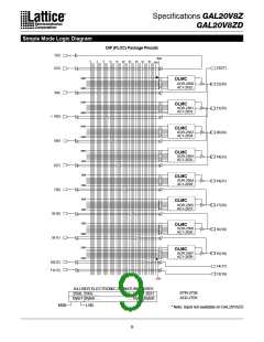
The JEDEC fuse numbers, including the User Electronic Signature
(UES) fuses and the Product Term Disable (PTD) fuses, are shown
on the logic diagram on the following page.
All registered macrocells share common clock and output enable
control pins. Any macrocell can be configured as registered or I/
O. Up to eight registers or up to eight I/Os are possible in this mode.
Dedicated input or output functions can be implemented as sub-
sets of the I/O function.
CLK
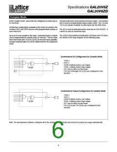
Registered Configuration for Registered Mode
- SYN=0.
- AC0=1.
- XOR=0 defines Active Low Output.
- XOR=1 defines Active High Output.
- AC1=0 defines this output configuration.
- Pin 1(2) controls common CLK for the registered
outputs.
D
Q
Q
XOR
- Pin 13(16) controls common OE for the registered
outputs.
- Pin 1(2) & Pin 13(16) are permanently configured as
CLK & OE for registered output configuration.
OE
Combinatorial Configuration for Registered Mode
- SYN=0.
- AC0=1.
- XOR=0 defines Active Low Output.
- XOR=1 defines Active High Output.
- AC1=1 defines this output configuration.
- Pin 1(2) & Pin 13(16) are permanently configured as
XOR
CLK & OE for registered output configuration.
Note: The development software configures all of the architecture control bits and checks for proper pin usage automatically.
4

 LATTICE [ LATTICE SEMICONDUCTOR ]