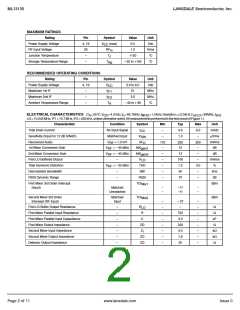
ML13135
LANSDALE Semiconductor, Inc.
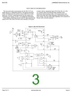
TEST CIRCUIT INFORMATION
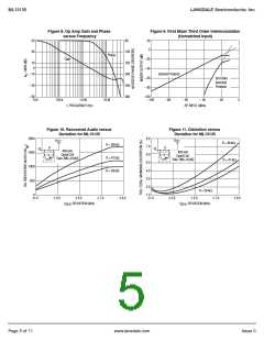
The recovered audio measurements for the ML13135 are
made with an LC quadrature detector. The typical recovered
audio will depend on the external circuit; either the Q of the
quad coil, or the RC matching network for the ceramic dis-
criminator. See Figures 10 and 11 for additional information.
is better with an unmatched input (50 Ω from Pin 21 to Pin
22). Typical values for both have been included in the
Electrical Characterization Table. TOI measurements were
taken at the pins with a high impedance probe/spectrum ana-
lyzer system. The first mixer input impedance was measured at
Since adding a matching circuit to the RF input increases the the pin with a network analyzer.
signal level to the mixer, the third order intercept (TOI) point
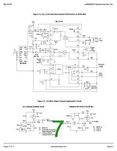
Figure 1a. ML13135 Test Circuit
V
CC
24
0.84
µH
1st LO
Varicap
0.01
Figure 1.
1
2
0.1
23
20 p
39.0
MHz
Xtal
1.0 k
0.001
22
21
5.0 p
62 pF
180 p
RF
Input
3
0.2 µH
V
1
5.0 k
CC
0.01
4
5
20
0.1
Ceramic
Filter
10.7 MHz
2nd LO
120 p
V
2
50 p
CC
6
7
19
0.1
10.245
MHz Xtal
360
18
8
Ceramic
Filter
455 kHz
9
AF
8.2 k
17
16
Demod
10
11
0.1
Limiter
0.1
0.1
39 k
15
14
13
0.1
12
0.1
39 k
455 kHz
Quad
Coil
Page 3 of 11
www.lansdale.com
Issue 0

 LANSDALE [ LANSDALE SEMICONDUCTOR INC. ]