2.5 GB/S CWDM SFP TRANSCEIVER
7
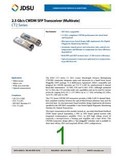
Optical Specifications
Parameter
40 km (PIN) at OC-48
80 km (APD) at OC-48
Average output power1
Minimum
0 dBm
0 dBm
Typical
1.5 dBm
4 dBm
0.5 dBm
1.5 dBm
3 dBm
1.5 dBm
4 dBm
0.5 dBm
1.5 dBm
3 dBm
Maximum
Minimum
Typical
Maximum
Minimum
Typical
BOL power output1
TX operating wavelength
Spectral width2
-6.5 nm
Center
-6.5 nm
Center
Maximum
Typical
6.5 nm
0.3 nm
6.5 nm
0.3 nm
Maximum
Minimum
Minimum
Typical
Maximum
Minimum
Maximum
Maximum
1 nm
30 dB
9.0 dB
1 nm
30 dB
9 dB
10 dB
Side mode suppression ratio (DFB laser)3
Extinction ratio4 (BOL)
10.0 dB
11.5 dB
8.2 dB
12.0 dB
200 ps
Compliant with GR-253
and ITU-T G.957
10%
11.5 dB
8.2 dB
12.0 dB
200 ps
Compliant with GR-253
and ITU-T G.957
10%
Extinction ratio4 (EOL)
Optical rise and fall times (20 to 80%)5
Eye mask of optical output
Eye mask margin (filtered)
Minimum
Typical
Maximum
Maximum
Typical
Maximum
Minimum
Typical
Minimum
Minimum
Minimum
Typical
15%
15%
Jitter generation (peak-to-peak)6
Jitter generation (rms)6
Power output with transmitter disabled
70 mUIP-P
7 mUIrms
-50 dBm
-40 dBm
-21 dBm
-23 dBm
-18 dBm
0 dBm
70 mUIP-P
7 mUIrms
-50 dBm
-40 dBm
-30 dBm
-32 dBm
-28 dBm
-8 dBm
3 µs
Receiver sensitivity (BOL, BER=1 x 10⁻¹⁰, ER=10 dB)
Receiver sensitivity (EOL, BER=1 x 10⁻¹⁰, ER=8.2 dB)
Maximum received optical power
Link status response time
3 µs
50 µs
50 µs
Maximum
Maximum
Maximum
Maximum
Minimum
Maximum
Maximum
100 µs
1.5 dB
1000 ps/nm
-27 dB
-24 dB
10-15
-24 dB
155 to 2700 Mb/s
100 µs
2.5 dB
1600 ps/nm
-27 dB
-24 dB
10-15
-24 dB
155 to 2700 Mb/s
Optical path penalty
Dispersion
Receiver reflectance
Minimum optical return loss
BER floor
Reflect into Tx for <1 dB degradation at the receiver
Bit rate
1. Fiber coupled power, connector repeatability is 1 dB.
2. Full spectral width measured 20 dB down from the central wavelength peak under fully modulated conditions (for DFB lasers).
3. Ratio of the average output power in the dominant longitudinal mode to the power in the most significant side mode under fully modulated conditions.
4. Ratio of logic 1 output power to logic 0 output power under fully modulated conditions. When operated at data rates below 1 Gb/s, the maximum extinction ratio
specification is increased by 2 dB.
5. Using an unfiltered measurement.
6. Formatted OC-48 pattern with scrambled PRBS 23 payload using Agilent Omni BER as the optical source driving an external OC-48 optical receiver with CDR. The
differential data outputs of this optical receiver with CDR. The differential dataoutputs of this optical receiver are used as the electrical inputs for the CT2 transmitter which
optically drives the Omni BER receiver input.

 JDSU [ JDSU ]