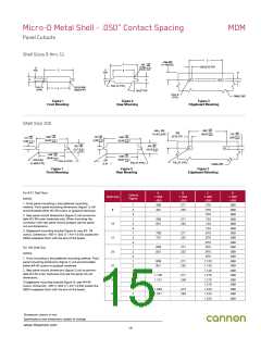
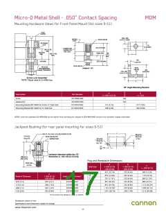
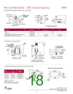
Micro-D Metal Shell - .050” Contact Spacing
Panel Cutouts
MDM
Shell Sizes 9 thru 51
C
.450±.002
+.005
C
A
.100
(2.54)
R TYP.
(11.43±0.05)
-.000
.030 (0.76) TYP.
+0.13)
-0.00
D
TYP.
C
D
TYP.
D
B
B
++
++
FULL R. (TYP.)
.015 (0.38)R.
MAX.(TYP)
FULL R.
(TYP.)
A
26˚/27˚TYP
FULL R.
(TYP.)
PANEL REF.
Figure 1
Front Mounting
Figure 2
Rear Mounting
Figure 3
Edgeboard Mounting
Shell Size 100
+.005
1.805
-.000
.450+_.002
+.005
.030
+0.13
-0.00
)
.118
-.000
(45.85
(11.43+_0.05)
+.005
+.005
+.005
-.000
+.005
(0.76) TYP.
+0.13
-0.00
1.805 -.000
.118
1.805 -.000
)
(3.00
.118
-.000
+0.13
-0.00
+0.13
-0.00
+0.13
-0.00
)
)
(45.85
(3.00
)
(45.85
+0.13 )
-0.00
(3.00
+.004
+.004
-.000
.361 -.000
.401
++
++
+0.10
-0.00
+0.10
)
(9.17
)
(10.18
-0.00
+.004
-.000
1.456
+.004
-.000
1.520
+0.10
-0.00
(36.98
)
+0.10
-0.00
)
(38.61
.015 (0.38)
R. MAX (TYP.)
.125
FULL R. (TYP.)
FULL R. (TYP.)
FULL R. (TYP.)
)
(3.18
PANEL REF.
Figure 1
Front Mounting
Figure 2
Rear Mounting
Figure 3
Edgeboard Mounting
For 9-51 Shell Sizes
NOTES:
A
B
C
D
Cutout
Figure
Shell Size
+.004
-.000
+.004
-.000
+.005
-.000
+.005
-.000
1. Front panel mounting is the preferred mounting
method. Front panel mounting dimensions (figure 1) will
accommodate either #2-56 screws or jackpost hardware.
1
2
3
1
2
3
1
2
3
1
2
3
1
2
3
1
2
3
1
2
3
.408
.401
-
.271
.252
-
.570
.570
.089
.089
.089
.089
.089
.089
.089
.089
.089
.089
.089
.089
.089
.089
.089
.089
.089
.089
.089
.089
.089
9
.570
2. Rear panel mount dimensions (figure 2) will accommo-
date #2-56 screw hardware only. When mounting the
connector with rear panel mount jackpost see the panel
cut-out dimensions.
.558
.551
-
.271
.252
-
.720
15
21
25
31
37
51
.720
.720
3. Edgeboard mounting bracket (figure 3) uses #2- 56
screws. Dimension .450+/-.002 (11.43+/-0.05) locates the
MDM receptacle flush with the end of the board.
.708
.701
-
.271
.252
-
.870
.870
.870
.808
.801
-
.271
.252
-
.970
For 100 Shell Size
NOTES:
.970
.970
1. Front mounting is the preferred mounting method. Front
panel mounting dimensions (figure 1) will accommodate
either #4-40 screws or jackpost hardware.
.958
.951
-
.271
.252
-
1.120
1.120
1.120
1.270
1.270
1.270
1.220
1.220
1.220
2. Rear panel mount dimensions (figure 2) will accommo-
date #4-40 screw hardware only see the panel cut-out
dimensions.
1.108
1.101
-
.271
.248
-
3.Edgeboard mounting bracket (figure 3) uses #4-40
screws. Dimension .450+/-.002 (11.43+/-0.05) locates the
MDM receptacle flush with the end of the board.
1.058
1.051
-
.315
.295
-
Dimensions shown in mm
Specifications and dimensions subject to change
www.ittcannon.com
15

 ITT [ ITT Cannon ]