Microstrips .050” Contact Spacing
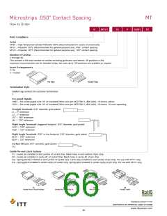
How to Order
MT
R
MTV1
-
16
P
H001
01
RoHS Compliance
Series
MTB1 – High Temperature Diallyl Phthalate 150°C (Recommended for severe environments)
MTV1 – Polyester 125°C (Recommended for general purpose use), .050” contact spacing
MTV2 – Polyester 125°C (Recommended for general purpose use), .100” contact spacing
Number of Cavities
2 through 40.
This number is the total number of cavities including guide pins and latches. 40 positions is the
maximum recommended size for standard strips, but sizes up to 120 positions are available on request.
Insert Arrangements
P- Pin
S – Socket
Pin Strip
Socket Strip
Termination Style
Solder Cup contacts for customer termination
S
Pre-wired Pigtails
H067 – Pre-wired pigtail with 18” of insulated Teflon wire per M22759/11, #26 AWG, 19 strand, yellow
HY01 – Pre-wired pigtail with 18” of insulated Teflon wire per M22759/11, #26 AWG, 19 strand, 10 color repeating
Straight Terminals .018” diameter, gold-plated
L1 – 5” extension
L2 – 1” extension
L57 – .190” extension
L61 – .125” extension
Right Angle Terminals staggered footprint .018” diameter, gold plated
AL57 – .190” extension
AL61 – .125” extension
Right Angle Terminals .050” in-line footprint .018” diameter, gold plated
BL57 – .190” extension
BL61 – .125” extension
Surface Mount .018” diameter, gold-plated
CL1
Guide Pin and Latch Options
01 – Guide pin installed in end cavities of socket strip. Blank holes in end cavities of pin strip.
02 – Guide pin installed in cavity #1 of socket Strip. Blank holes in cavity #1 of pin strip.
03 – Spring latches installed in end cavities of socket strip. Latch clips installed in end cavities of pin strip. For use with MTV1 only.
04 – Spring latch installed in center cavity of socket strip. Spring latch installed in center cavity of pin strip. For use with MTV1 only.
01
02
03
04
Guide Pins In End Cavities
Guide Pins In Cavity #1
End Latches
Center Latch
Dimensions shown in mm
Specifications and dimensions subject to change
www.ittcannon.com
66

 ITT [ ITT Cannon ]