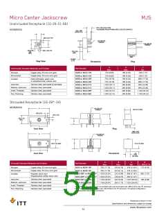
Micro-D Plastic Shell - .050” Contact Spacing
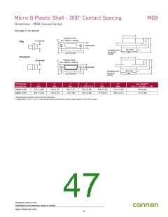
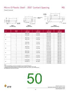
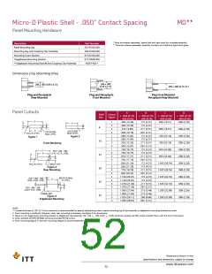
Panel Cutouts
MD
C
.450 ±.002
(11.43 ±0.05)
.030 (0.76) TYP.
C
D
+ .005 (0.13) R TYP
- .000 (0.00)
.075 (1.91)
D
TYP.
A
C
D
++
++
B
B
FULL R. (TYP.)
FULL R.
(TYP.)
.015 (0.38)R.
MAX.(TYP)
FULL R.
(TYP.)
PANEL REF.
A
26˚/27˚TYP
Figure 2
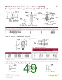
Rear Mounting
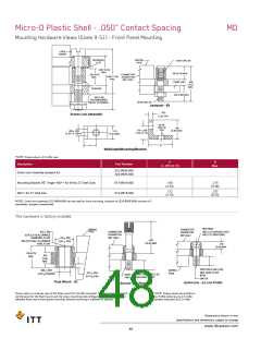
Figure 1
Front Mounting
Figure 3
Edgeboard Mounting
A
B
C
D
Cutout
Figure
Size
9
+ .004 (0.10)
+ .004 (0.10)
- .000 (0.00)
+ .005 (0.13)
- .000 (0.00)
+ .005 (0.13)
- .000 (0.00)
- .000 (0.00)
.409 (10.39)
.379 ( 9.63)
-
1
2
3
1
2
3
1
2
3
1
2
3
1
2
3
1
2
3
1
2
3
.172 (4.37)
.219 (5.56)
-
.570 (14.48)
.570 (14.48)
.570 (14.48)
.720 (18.29)
.720 (18.29)
.720 (18.29)
.870 (22.10)
.870 (22.10)
.870 (22.10)
.970 (24.64)
.970 (24.64)
.970 (24.64)
1.120 (28.45)
1.120 (28.45)
1.120 (28.45)
1.270 (32.26)
1.270 (32.26)
1.270 (32.26)
1.220 (30.99)
1.220 (30.99)
1.220 (30.99)
.089 (2.26)
.089 (2.26)
.089 (2.26)
.089 (2.26)
.089 (2.26)
.089 (2.26)
.089 (2.26)
.089 (2.26)
.089 (2.26)
.089 (2.26)
.089 (2.26)
.089 (2.26)
.089 (2.26)
.089 (2.26)
.089 (2.26)
.089 (2.26)
.089 (2.26)
.089 (2.26)
.089 (2.26)
.089 (2.26)
.089 (2.26)
.559 (14.20)
.529 (13.44)
-
.172 (4.37)
.219 (5.56)
-
15
21
25
31
37
51
.709 (18.00)
.679 (17.25)
-
.172 (4.37)
.219 (5.56)
-
.809 (20.55)
.779 (19.79)
-
.172 (4.37)
.219 (5.56)
-
.959 (24.36)
.929 (23.60)
-
.172 (4.37)
.219 (5.56)
-
1.109 (28.17)
1.079 (27.41)
-
.172 (4.37)
.219 (5.56)
-
1.059 (26.90)
1.029 (26.14)
-
.215 (5.46)
.261 (6.63)
-
NOTE:
1. Front mounting (figure 1) and rear mounting (figure 2) accommodates #2-56 screws.
2. Front mounting is preferred. However, when rear mounting is necessary. use detail on previous page.
3. Edgeboard mounting bracket (figure3) uses #2-56 screws. Dimension .450 ± .002 (11.43 ± 0.05) locates the
MD receptacle flush with the end of the board.
Dimensions shown in mm
Specifications and dimensions subject to change
www.ittcannon.com
50

 ITT [ ITT Cannon ]