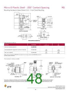
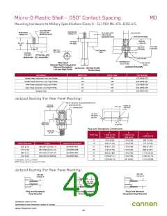
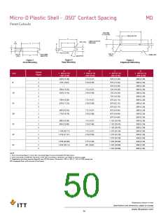
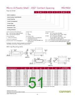
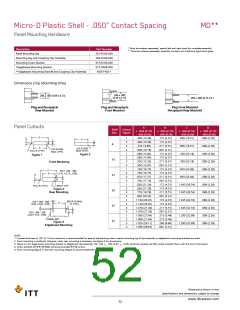
Micro-D Plastic Shell - .050” Contact Spacing
Panel Mounting Hardware
MD**
* Must be ordered separately; specify left and right hand for complete assembly.
** Must be ordered separately; assembly contains set of left and right hand types.
Description
Part Number
201-9100-000
294-9100-000
015-9100-000
015-5009-000
MD51428-1
Panel Mounting Key
Mounting Key and Coupling Clip Assembly
Mounting Screw Bracket
*Edgeboard Mounting Bracket
**Edgeboard Mounting Bracket and Coupling Clip Assembly
Dimensions (Clip Mounting Only)
.330 ± .005
(8.38 ± 0.13)
.200 ± .005 (5.08 ± 0.13)
.265 ± .005 (6.73 ± 0.1
Plug and Receptacle
Rear Mounted
Plug and Receptacle
Front Mounted
Plug Front Mounted
Receptacle Rear Mounted
Panel Cutouts
A
B
C
D
Shell
Size
Cutout
Figure
+ .004 (0.10)
- .000 (0.00)
+ .004 (0.10)
- .000 (0.00)
+ .004 (0.10)
- .000 (0.00)
.650 (16.51)
+ .005 (0.13)
- .000 (0.00)
.089 (2.26)
C
D
1
2
3
4
1
2
3
4
1
2
3
4
1
2
3
4
1
2
3
4
1
2
3
4
.408 (10.36)
.408 (10.36)
.378 ( 9.60)
.400 (10.16)
.588 (14.94)
.588 (14.94)
.528 (13.28)
.550 (13.97)
.738 (18.75)
.738 (18.75)
.678 (17.27)
.700 (17.78)
.838 (21.29)
.838 (21.29)
.778 (19.76)
.800 (20.32)
1.138 (28.91)
1.138 (28.91)
1.078 (27.38)
1.078 (27.38)
1.088 (27.64)
1.088 (27.64)
1.028 (26.11)
1.050 (26.67)
.172 (4.37)
.172 (4.37)
.217 (5.51)
.091 (2.31)
.172 (4.37)
.172 (4.37)
.217 (5.51)
.091 (2.31)
.172 (4.37)
.172 (4.37)
.217 (5.51)
.091 (2.31)
.172 (4.37)
.172 (4.37)
.217 (5.51)
.091 (2.31)
.172 (4.37)
.172 (4.37)
.217 (5.51)
.091 (2.31)
.215 (5.46)
.215 (5.46)
.260 (6.60)
.091 (2.31)
A
-
-
B
B
9
.650 (16.51)
.089 (2.26)
A
.015 (0.38)R.
MAX. (TYP.)
.015 (0.38)R.
MAX. (TYP.)
-
-
FULL R. (TYP.)
.795 (20.19)
.089 (2.26)
Figure 2
Figure 1
-
-
15
21
25
37
51
.795 (20.19)
.089 (2.26)
Front Mounting
-
-
.945 (24.00)
.089 (2.26)
C
.075 + .005 - .000
(1.91 + 0.13 _ 0.00)
-
-
A
D
.945 (24.00)
.089 (2.26)
B
-
-
1.045 (26.54)
.089 (2.26)
FULL R. (TYP.)
26˚/27˚ TYP.
-
-
Figure 3
Rear Mounting
1.045 (26.54)
.089 (2.26)
-
-
1.345 (34.16)
.089 (2.26)
.005 (0.13) MAX.
R. (TYP.)
.018 + .002 - .000
(0.46 + 0.05 - 0.00)
A
-
-
1.345 (34.16)
.089 (2.26)
B
-
-
.182 + .004 - .000
(4.62 + 0.10 - 0.00)
1.295 (32.89)
.089 (2.26)
PANEL REF.
-
-
Figure 4
Edgeboard Mounting
1.295 (32.89)
-
.089 (2.26)
-
NOTE:
1. A panel thickness of 1/8” (3.17mm) maximum is recommended for ease of tab bending when a panel mounting key & clip assembly or edgeboard mounting brackets are used.
2. Front mounting is preferred. However, when rear mounting is necessary, use figure 3 for dimensions.
3. Figure 4 is for edge board mounting bracket or edgeboard clip assembly. The .184 +_ .002 (2.67 +_ 0.05) dimension locates the MD socket insulator flush with the end of the board.
4. Screw brackets (015-9100-000) will accommodate #2-56 screws.
5. Front mounting (Figure 1) and rear mounting (Figure 3) accommodate #2-56 screws.
Dimensions shown in mm
Specifications and dimensions subject to change
www.ittcannon.com
52

 ITT [ ITT Cannon ]