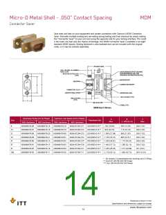
Micro-D Metal Shell - .050” Contact Spacing
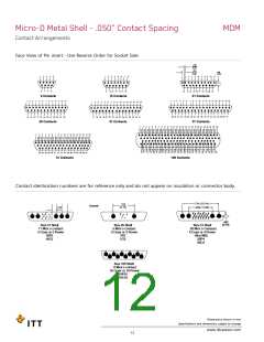
Contact Arrangements
MDM
Face View of Pin insert - Use Reverse Order for Socket Side
.025
(0.64)
TYP.
.050
(1.27)
TYP.
.043
(1.09)
1
2
3
4
5
1
2
3
4
5
6
7
8
1
2
3
4
5
6
7
8
9
10 11
6
7
8
9
9
10 11 12 13 14 15
12 13 14 15 16 17 18 19 20 21
9 Contacts
15 Contacts
21 Contacts
1
2
3
4
5
6
7
8
9
10 11 12 13 14 15 16 17 18 19
1
2
3
4
5
6
7
8
9
10 11 12 13
1
2
3
4
5
6
7
8
9
10 11 12 13 14 15 16
20 21 22 23 24 25 26 27 28 29 30 31 32 33 34 35 36 37
14 15 16 17 18 19 20 21 22 23 24 25
17 18 19 20 21 22 23 24 25 26 27 28 29 30 31
25 Contacts
31 Contacts
37 Contacts
1
2
3
4
5
6
7
8
9 10 11 12 13 14 15 16 17 18 19 20 21 22 23 24 25 26
27 28 29 30 31 32 33 34 35 36 37 38 39 40 41 42 43 44 45 46 47 48 49 50 51
1
2
3
4
5
6
7
8
9
10 11 12 13 14 15 16 17 18
19 20 21 22 23 24 25 26 27 28 29 30 31 32 33 34 35
52 53 54 55 56 57 58 59 60 61 62 63 64 65 66 67 68 69 70 71 72 73 74 75
76 77 78 79 80 81 82 83 84 85 86 87 88 89 90 91 92 93 94 95 96 97 98 99 100
36 37 38 39 40 41 42 43 44 45 46 47 48 49 50 51
51 Contacts
100 Contacts
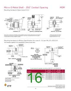
Contact identication numbers are for reference only and do not appear on insulation or connector body.
.714 (18.14)
.460 (11.68)
.320
(8.13)
Coaxial
.103
12
89
34
56
7
A1
A2
A3
A4
1
8
23
91
4
12
45
3
A1
A2
A3
A4
A5
A1
A2
10 11 12 13
56
7
14 15 16 17 18 19 20
0
11
.007
(0.18)
Size 51 Shell
Size 25 Shell
Size 51 Shell
11 Micro contact
5 Coax or 5 Power
16P5
5 Micro contact
2 Coax or 2 Power
7P2
20 Micro contacts
4 Coax or 4 Power
(Not MS)
25P4
16C5
7C2
25C4
A1
A2
A3
A4
A5
A6
A7
A8
A9
A10
Size 100 Shell
0 Micro contact
10 Coax or 10 Power
10P10
10C10
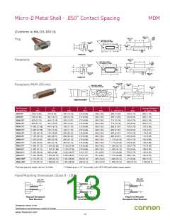
Dimensions shown in mm
Specifications and dimensions subject to change
www.ittcannon.com
12

 ITT [ ITT Cannon ]