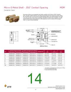
Micro-D Metal Shell - .050” Contact Spacing
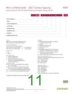
How to Order (For MIL-DTL-83513 ordering information, see pp. 29-30)
MDM
-
P
-
XXX
R
MDM
51
P
H
001
RoHS Compliance
Series
Contact Arrangements
Contact Type
Termination Type
Termination Code
Hardware
Shell Finish Mod Codes
Series
Hardware
MDM: (Size 9-100) Liquid Crystal Polymer (LCP)
MDM: (Combo Layout) Diallyl Phthalate (DAP)
M - Military specification hardware, see page 16
for military hardware codes.
P - Jackpost
K - Jackscrew-standard profile
L - Jackscrew-low profile
Contact Arrangements
9-15-21-25-31-37-51-100 (standard)
16C5, 10C10, 7C2, 24C4 (coaxial)
16P5, 10P10, 7P2, 24P4 (power)
or combination of
coax and power
F - Float mount
B - No hardware standard.091 (2.31) dia. hole for
sizes 9-51; .120 (3.05) dia. hole for size 100.
A - .125 (3.18) dia. mounting holes for sizes 9-51;
.166 (4.22) dia. hole for size 100.
Contact Type
P - Pin
S - Socket
B1 - .1475 (3.75) dia. hole for size 100 (Per MIL-DTL-83513)
Termination Type
Shell Finish Modification Codes
No Number - (Standard cadmium/yellow chromate over nickel
A174 - Electroless nickel
A172 - Gold over nickel
A141 - Irridite/alodine
H - Harness-insulated wire.
L - Solid-uninsulated wire.
S - Solder pot to accept #26 AWG MAX.
harness wire. (Not available with power
contact arrangements.)
A30 - Black anodize
Termination code*
(H) 001 - 18”,7/34 strand,#26 AWG, MIL-W-16878/4,
Type E Teflon, yellow.
(H) 003 - 18”, 7/34 strand, #26 AWG, MIL-W-16878/4,
Type E Teflon, color coded to MIL-STD-681 System I.
(L) 1 - 1/2” uninsulated solid #25 AWG gold plated copper.
(L) 2 - 1” uninsulated solid #25 AWG gold plated copper.
Modification Codes
F222 - High Temp (200°C)
F234 - 24 AWG Wire
A295 - Non-Magnetic
K135 - F222 and A295
A214 - Hot tin dip
K139 - F222 High (200°C) and F234 (24 AWG Wire)
For additional termination codes, please see pages 79-81.
Dimensions shown in mm
Specifications and dimensions subject to change
www.ittcannon.com
11

 ITT [ ITT Cannon ]