Micro-D Metal Shell - .050” Contact Spacing
MDM
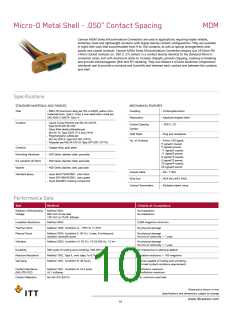
Cannon MDM Series Microminiature Connectors are used in applications requiring highly reliable,
extremely small and lightweight solutions with higher density contact configurations. They are available
in eight shell sizes that accommodate from 9 to 100 contacts, as well as special arrangements with
power and coaxial contacts. Cannon MDM Series Microminiature Connectors employ size 24 Micro-Pin
/ Micro-Socket Contacts on .050 (1.27) centers in a contact density identical to the standard Micro-D
connector series, but with Aluminum shells to increase strength, prevent chipping, cracking or breaking
and provide electromagnetic (EMI and RFI shielding. They also feature a silicone elastomer compression
interfacial seal to provide a moisture and humidity seal between each contact and between the contacts
and shell.
Specifications
STANDARD MATERIALS AND FINISHES
MECHANICAL FEATURES
Shell
- 6061-T6 Aluminum alloy per QQ-A-200/8, yellow chro-
mate/cadmium, Type II, Class 3 over electroless nickel per
SAE AMS-C-26074, Class 4.
Coupling
- Friction/jackscrews
- Keystone-shaped shells
- .050 (1.27)
Polarization
Insulator
- Liquid Crystal Polymer per MIL-M-24519,
Type GLCP-30F (9-100)
- Glass filled diallyl phthalate per
MIL-M-14, Type SDGF (7*2 and 24*4)
- Polyphenylene sulfide per
Contact Spacing
Centers
Shell Styles
- Plug and receptacle
MIL-M-24519, Type GST-40F (16*5)
- Polyester per MIL-M-24519, Type GPT-30F (10*10)
No. of Contacts
- 9 thru 100 signal;
5 signal/2 coaxial;
5 signal/2 power;
11 signal/5 coaxial;
11 signal/5 power;
0 signal/10 coaxial;
0 signal/10 power;
20 signal/4 coaxial;
20 signal/4 power
Contacts
- Copper alloy, gold plate
Mounting Hardware
Kit, Jackpost (3) items
Washer
- 300 Series stainless steel, passivate
- 300 Series stainless steel, passivate
- 400 Series stainless stell, passivate
Coaxial Cable
Wire Size
- RG - 178/U
Standard Epoxy
- Hysol EE4215/HD3561, color black
- Hysol EE4198/HD3561, color green
- Hysol MG40FS molding compound
- #24 thru #32 AWG
- Multiple indent crimp
Contact Termination
Performance Data
Test
Method
Criteria of Acceptance
Dielectric Withstanding
Voltage
Method 3001:
600 VAC at sea level
150 VAC at 70,00’ altitude
No breakdown
No breakdown
Insulation Resistance
Thermal Shock
Method 3003
5,000 megohms minimum
No physical damage
Method 1003. Condition A: - 55°C to +125°C
Physical Shock
Method 2004, Condition E: 50 G’s, 3 axes, 6 millisecond
duration sawtooth pulse
No physical damage
No loss of continuity > 1 μsec
Vibration
Method 2005, Condition IV: 20 G’s, 10-20,000 Hz. 12 hrs
No physical damage
No loss of continuity > 1 μsec
Durability
500 cycles of mating and unmating, 500 CPH max.
Method 1002, Type II, omit steps 7a & 7b
Method 1001, Condition B: 48 hours
No mechanical or electrical defects
Insulation resistance > 100 megohms
Moisture Resistance
Salt Spray
Shall be capable of mating and unmating,
and meet contact resistance requirements
Contact Resistance
(MIL-STD-202)
Method 1001, Condition B: At 3 amps
At 1 milliamp
8 milliohms maximum
10 milliohms maximum
Contact Retention
Per MIL-DTL-83513
5 lb. minimum axial load
Dimensions shown in mm
Specifications and dimensions subject to change
www.ittcannon.com
10

 ITT [ ITT Cannon ]