D Subminiature
ZD*
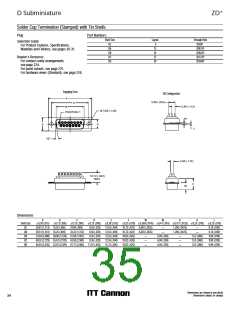
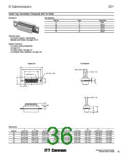
Solder Cup Termination (Stamped) with Tin Shells
Receptacle
Part Numbers
Shell Size
Layout
9
Through Hole
ZDE9S
DE
DA
DB
DC
DD
15
ZDA15S
ZDB25S
ZDC37S
ZDD50S
25
37
50
Selection Guide
ɀ For Product Features, Specifications,
Materials and Finishes, see pages 30-31.
Reader’s Resource
ɀ For contact cavity arrangements,
see page 224.
ɀ For panel cutouts, see page 221.
ɀ For hardware views (Standard), see page 226.
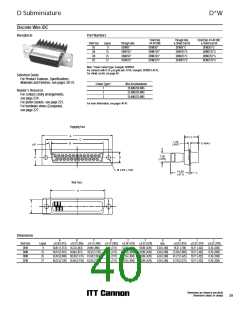
Engaging Face
DD Configuration
A
C
5,69 (.224)
B
2,84 (.112)
Ø 3,05 (.120)
POSITION 1
K
E
D
L
10°
2,84 (.112)
10,72 (.422)
MAX
F
W
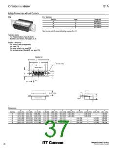
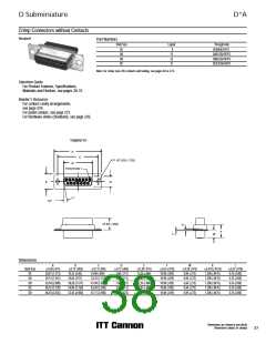
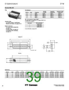
Dimensions
A
B
C
D
E
F
W
K
L
Shell Size
DE
0,38 (.015)
0,13 (.005)
0,13 (.005)
0,13 (.005)
0,38 (.015)
0,25 (.010)
0,38 (.015)
0,318 (.0125)
1,206 (.0475)
1,206 (.0475)
1,206 (.0475)
1,206 (.0475)
1,206 (.0475)
0,25 (.010)
30,81 (1.213)
39,14 (1.541)
53,04 (2.088)
69,32 (2.729)
66,93 (2.635)
16,33 (.643)
24,66 (.971)
38,38 (1.511)
54,84 (2.159)
52,42 (2.064)
24,99 (.984)
33,32 (1.312)
47,04 (1.852)
63,50 (2.500)
61,11 (2.406)
7,90 (.311)
7,90 (.311)
7,90 (.311)
7,90 (.311)
10,74 (.423)
12,55 (.494)
12,55 (.494)
12,55 (.494)
12,55 (.494)
15,37 (.605)
10,90 (.429)
10,90 (.429)
10,90 (.429)
10,90 (.429)
10,90 (.429)
6,94 (.273)
6,94 (.273)
6,94 (.273)
6,94 (.273)
6,94 (.273)
0,76 (.030)
0,76 (.030)
0,76 (.030)
0,76 (.030)
0,76 (.030)
DA
DB
DC
DD
Dimensions are shown in mm (inch)
Dimensions subject to change
35

 ITT [ ITT Cannon ]