IRLML6402PbF-1
4.0
3.0
2.0
1.0
0.0
25
20
15
10
5
I
D
TOP
-1.7A
-3.0A
BOTTOM -3.7A
0
25
50
75
100
125
150
25
50
75
100
125
150
°
°
T , Case Temperature ( C)
Starting T , Junction Temperature ( C)
C
J
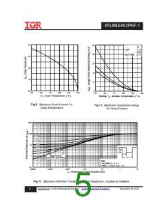
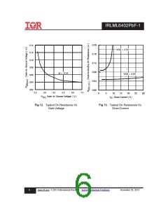
Fig 9. Maximum Drain Current Vs.
Fig 10. Maximum Avalanche Energy
Case Temperature
Vs. Drain Current
1000
100
10
D = 0.50
0.20
0.10
0.05
P
2
DM
0.02
0.01
t
1
SINGLE PULSE
(THERMAL RESPONSE)
1
t
2
Notes:
1. Duty factor D =
t / t
1
2. Peak T =P
J
x Z
+ T
thJA A
DM
0.1
0.00001
0.0001
0.001
0.01
0.1
1
10
t , Rectangular Pulse Duration (sec)
1
Fig 11. Maximum Effective Transient Thermal Impedance, Junction-to-Ambient
5
www.irf.com © 2013 International Rectifier Submit Datasheet Feedback
November 25, 2013

 INFINEON [ Infineon ]