IRK.41, .56 Series
Bulletin I27131 rev. G 10/02
130
120
110
100
90
130
120
110
100
90
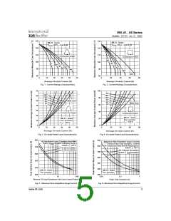
IRK.41.. Se rie s
IRK.41.. Se rie s
(DC) = 0.46 K/W
R
(DC) = 0.46 K/W
R
thJC
thJC
C o nd uc tio n Angle
Co nd uc tio n Pe rio d
30°
60°
30°
60°
90°
90°
120°
120°
40
180°
180°
DC
60
80
80
0
10
20
30
40
50
0
20
80
Ave ra g e On-sta te Curre nt (A)
Ave ra g e On-sta te Curre nt (A)
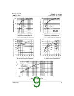
Fig. 1 - Current Ratings Characteristics
Fig. 2 - Current Ratings Characteristics
70
60
50
40
30
20
10
0
100
80
60
40
20
0
DC
180°
120°
90°
60°
30°
180°
120°
90°
60°
30°
RMS Lim it
RMS Lim it
C o nd uc tio n Ang le
C ond uc tio n Pe rio d
IRK.41.. Se rie s
Pe r Junc tion
= 125°C
IRK.41.. Se rie s
Pe r Junc tion
= 125°C
T
T
J
J
0
10
20
30
40
50
0
20
40
60
80
Ave ra g e On-sta te Curre nt (A)
Ave ra g e O n-sta te Curre nt (A)
Fig. 4 - On-state Power Loss Characteristics
Fig. 3 - On-state Power Loss Characteristics
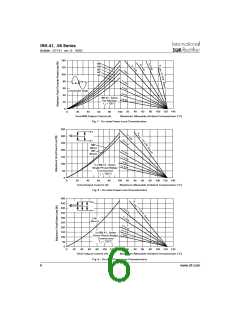
800
700
600
500
400
300
900
At Any Ra te d Loa d Cond ition And With
Ma ximum Non Re p e titive Surg e Curre nt
Ve rsus Pulse Tra in Dura tion. Control
Of Cond uc tio n Ma y Not Be Ma inta ine d .
Ra te d V
Ap p lie d Following Surg e .
RRM
Initia l T = 125°C
J
800
700
600
500
400
300
@ 60 Hz 0.0083 s
@ 50 Hz 0.0100 s
Initia l T = 125°C
J
No Volta g e Re a p p lie d
Ra te d V
Re a p p lie d
RRM
IRK.41.. Se rie s
Pe r Junc tio n
IRK.41.. Se rie s
Pe r Junc tion
1
10
100
0.01
0.1
Pulse Tra in Dura tion (s)
1
Num b e r O f Eq ua l Am p litud e Ha lf C yc le Curre nt Pulse s (N)
Fig. 5 - Maximum Non-Repetitive Surge Current
Fig. 6 - Maximum Non-Repetitive Surge Current
www.irf.com
5

 INFINEON [ Infineon ]