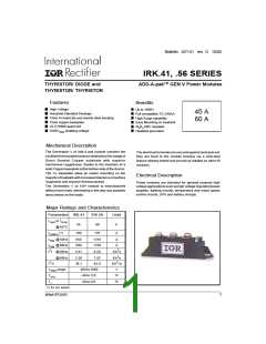
IRK.41, .56 Series
Bulletin I27131 rev. G 10/02
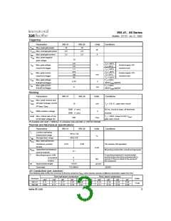
Triggering
Parameters
IRK.41
10
IRK.56
10
Units
Conditions
PGM Max.peakgatepower
W
A
PG(AV) Max.averagegatepower
2.5
2.5
IGM
Max.peakgatecurrent
2.5
2.5
-VGM Max.peaknegative
gate voltage
10
4.0
2.5
1.7
TJ =-40°C
TJ =25°C
TJ =125°C
V
VGT Max.gatevoltage
required to trigger
Anodesupply=6V
resistive load
270
150
80
TJ =-40°C
TJ =25°C
IGT
Max.gatecurrent
required to trigger
Anodesupply=6V
resistive load
mA
TJ =125°C
TJ =125oC,
ratedVDRMapplied
VGD Max.gatevoltage
thatwillnottrigger
0.25
6
V
TJ =125oC,
ratedVDRMapplied
IGD
Max.gatecurrent
thatwillnottrigger
mA
Blocking
Parameters
IRK.41
IRK.56
Units
mA
Conditions
IRRM Max. peak reverse and
IDRM off-state leakage current
at VRRM, VDRM
15
TJ = 125 oC, gate open circuit
2500 (1 min)
3500 (1 sec)
50 Hz, circuit to base, all terminals
shorted
VINS RMS isolation voltage
V
dv/dt Max. critical rate of rise
of off-state voltage (5)
TJ = 125oC, linear to 0.67 VDRM
gate open circuit
,
500
V/µs
(5) Available with dv/dt = 1000V/µs, to complete code add S90 i.e. IRKT41/16AS90.
Thermal and Mechanical Specifications
Parameters
IRK.41
IRK.56
Units
°C
Conditions
TJ
T
Junction operating
temperature range
Storage temp. range
- 40 to 125
-40to125
stg
RthJC Max. internalthermal
resistance, junction
tocase
0.23
0.20
Permodule, DCoperation
K/W
Nm
RthCS Typicalthermalresistance
case to heatsink
Mounting surface flat, smooth and greased
0.1
T
Mounting torque ± 10%
to heatsink
A mounting compound is recommended
and the torque should be rechecked after a
period of 3 hours to allow for the spread of
the compound
5
3
busbar
wt
Approximateweight
110(4)
gr(oz)
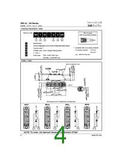
Casestyle
TO-240AA
JEDEC
∆R Conduction (per Junction)
(The following table shows the increment of thermal resistance RthJC when devices operate at different conduction angles than DC)
Sine half wave conduction
Rect. wave conduction
Devices
Units
°C/W
180o
0.11
0.09
120o
0.13
0.11
90o
0.17
0.13
60o
0.23
0.18
30o
0.34
0.27
180o
0.09
0.07
120o
0.14
0.11
90o
0.18
0.14
60o
0.23
0.19
30o
0.34
0.28
IRK.41
IRK.56
www.irf.com
3

 INFINEON [ Infineon ]