IR11682S
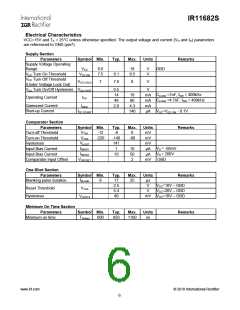
Electrical Characteristics
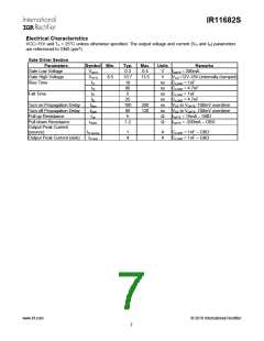
VCC=15V and TA = 25°C unless otherwise specified. The output voltage and current (VO and IO) parameters
are referenced to GND (pin7).
Supply Section
Parameters
Supply Voltage Operating
Range
Symbol Min.
Typ.
Max.
Units
Remarks
VCC
8.6
7.5
18
V
V
GBD
VCC Turn On Threshold
VCC Turn Off Threshold
(Under Voltage Lock Out)
VCC ON
8.1
7.6
8.5
VCC UVLO
7
8
V
VCC Turn On/Off Hysteresis VCC HYST
0.5
14
V
C
C
LOAD =1nF, fSW = 400kHz
LOAD =4.7nF, fSW = 400kHz
18
60
mA
mA
mA
Operating Current
ICC
48
Quiescent Current
Start-up Current
IQCC
2.6
4.3
140
ICC START
µA VCC=VCC ON - 0.1V
Comparator Section
Parameters
Turn-off Threshold
Turn-on Threshold
Hysteresis
Symbol Min.
Typ.
-6
Max.
0
Units
mV
mV
mV
µA
Remarks
VTH1
VTH2
-12
-220
-140
141
1
-80
VHYST
IIBIAS1
IIBIAS2
VOFFSET
VD = -50mV
VD = 200V
GBD
Input Bias Current
10
50
2
Input Bias Current
10
µA
Comparator Input Offset
mV
One-Shot Section
Parameters
Blanking pulse duration
Symbol Min.
tBLANK
Typ.
17
Max.
25
Units
µs
Remarks
8
2.5
5.4
40
V
V
VCC=10V – GBD
VCC=20V – GBD
Reset Threshold
Hysteresis
VTH3
mV VCC=10V – GBD
VHYST3
Minimum On Time Section
Parameters
Minimum on time
Symbol Min.
TOnmin
Typ.
Max.
Units
Remarks
600
850
1100
ns
www.irf.com
© 2010 International Rectifier
6

 INFINEON [ Infineon ]