IR11682S
Absolute Maximum Ratings
Absolute maximum ratings indicate sustained limits beyond which damage to the device may occur. All
voltage parameters are absolute voltages referenced to COM, all currents are defined positive into any lead.
The thermal resistance and power dissipation ratings are measured under board mounted and still air
conditions.
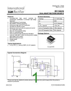
Parameters
Supply Voltage
Cont. Drain Sense Voltage
Pulse Drain Sense Voltage
Source Sense Voltage
Gate Voltage
Operating Junction Temperature
Storage Temperature
Thermal Resistance
Package Power Dissipation
Switching Frequency
Symbol
VCC
VD
VD
VS
VGATE
TJ
TS
Min.
-0.3
-1
-5
-3
-0.3
-40
-55
Max.
20
200
200
20
Units
V
V
V
V
V
°C
°C
Remarks
20
VCC=20V, Gate off
150
150
128
970
400
RθJA
PD
fsw
°C/W
mW
kHz
SOIC-8
SOIC-8, TAMB=25°C
Recommended Operating Conditions
For proper operation the device should be used within the recommended conditions.
Symbol
VCC
VD1, VD2
TJ
Definition
Min.
8.6
-3 †
-25
---
Max.
18
200
125
400
Units
Supply voltage
Drain Sense Voltage
V
Junction Temperature
Switching Frequency
°C
kHz
Fsw
-3V negative spike width 100ns
† VD1, VD2
≤
www.irf.com
© 2010 International Rectifier
5

 INFINEON [ Infineon ]