X9428
A.C. TEST CONDITIONS
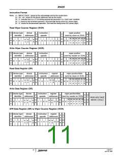
Circuit #3 SPICE Macro Model
Input pulse levels
V
x 0.1 to V
x 0.5
x 0.9
CC
CC
R
TOTAL
Input rise and fall times
Input and output timing level
10ns
R
R
L
H
C
V
L
CC
C
H
C
W
10pF
EQUIVALENT A.C. LOAD CIRCUIT
10pF
25pF
5V
2.7V
R
W
1533Ω
SDA Output
100pF
100pF
AC TIMING (over recommended operating conditions)
Symbol Parameter
Min.
100
2500
600
1300
600
600
600
100
30
Max.
Unit
kHz
ns
ns
ns
ns
ns
ns
ns
ns
ns
ns
ns
ns
ns
ns
ns
ns
f
Clock frequency
400
SCL
t
Clock cycle time
CYC
t
Clock high time
HIGH
t
Clock low time
LOW
t
Start setup time
SU:STA
HD:STA
SU:STO
t
Start hold time
t
Stop setup time
t
SDA data input setup time
SDA data input hold time
SCL and SDA rise time
SCL and SDA fall time
SU:DAT
t
HD:DAT
t
300
300
900
R
t
F
t
SCL low to SDA data output valid time
SDA data output hold time
AA
DH
t
50
50
T
Noise suppression time constant at SCL and SDA inputs
Bus free time (prior to any transmission)
WP, A0, A1, A2 and A3 setup time
I
t
1300
0
BUF
t
SU:WPA
HD:WPA
t
WP, A0, A1, A2 and A3 hold time
0
FN8197.1
April 26, 2006
15

 INTERSIL [ Intersil ]