HIP4082
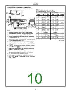
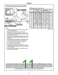
Dual-In-Line Plastic Packages (PDIP)
E16.3 (JEDEC MS-001-BB ISSUE D)
16 LEAD DUAL-IN-LINE PLASTIC PACKAGE
N
E1
INDEX
AREA
INCHES MILLIMETERS
1 2
3
N/2
SYMBOL
MIN
MAX
0.210
-
MIN
-
MAX
5.33
-
NOTES
-B-
-C-
A
A1
A2
B
-
4
-A-
0.015
0.115
0.014
0.045
0.008
0.735
0.005
0.300
0.240
0.39
2.93
0.356
1.15
0.204
18.66
0.13
7.62
6.10
4
D
E
BASE
PLANE
0.195
0.022
0.070
0.014
0.775
-
4.95
0.558
1.77
0.355
19.68
-
-
A2
A
-
SEATING
PLANE
L
C
L
B1
C
8, 10
D1
B1
-
eA
A1
A
D1
e
D
5
C
eC
B
eB
D1
E
5
0.010 (0.25)
C
B
S
M
0.325
0.280
8.25
7.11
6
NOTES:
E1
e
5
1. Controlling Dimensions: INCH. In case of conflict between
English and Metric dimensions, the inch dimensions control.
0.100 BSC
0.300 BSC
2.54 BSC
7.62 BSC
-
e
e
6
A
B
2. Dimensioning and tolerancing per ANSI Y14.5M-1982.
-
0.430
0.150
-
10.92
3.81
7
3. Symbols are defined in the “MO Series Symbol List” in Section
2.2 of Publication No. 95.
L
0.115
2.93
4
9
N
16
16
4. Dimensions A, A1 and L are measured with the package seated
in JEDEC seating plane gauge GS-3.
Rev. 0 12/93
5. D, D1, and E1 dimensions do not include mold flash or protru-
sions. Mold flash or protrusions shall not exceed 0.010 inch
(0.25mm).
e
6. E and
pendicular to datum
7. e and e are measured at the lead tips with the leads uncon-
are measured with the leads constrained to be per-
A
-C-
.
B
C
strained. e must be zero or greater.
C
8. B1 maximum dimensions do not include dambar protrusions.
Dambar protrusions shall not exceed 0.010 inch (0.25mm).
9. N is the maximum number of terminal positions.
10. Corner leads (1, N, N/2 and N/2 + 1) for E8.3, E16.3, E18.3,
E28.3, E42.6 will have a B1 dimension of 0.030 - 0.045 inch
(0.76 - 1.14mm).
10

 INTERSIL [ Intersil ]