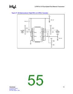
LXT971A 3.3V Dual-Speed Fast Ethernet Transceiver
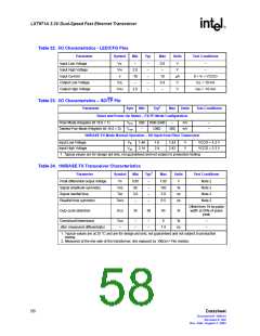
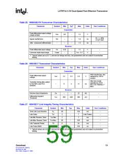
Table 25. 100BASE-FX Transceiver Characteristics
1
Parameter
Symbol
Min
Typ
Max
Units
Test Conditions
Transmitter
Peak differential output voltage
(single ended)
VOP
0.6
–
1.5
V
–
10 <–> 90%
2.0 pF load
Signal rise/fall time
TRF
–
–
–
–
–
1.9
1.3
ns
ns
Jitter (measured differentially)
–
Receiver
Peak differential input voltage
Common mode input range
VIP
0.55
–
–
–
1.5
V
V
–
–
VCMIR
VCC - 0.7
1. Typical values are at 25 °C and are for design aid only; not guaranteed and not subject to production
testing.
Table 26. 10BASE-T Transceiver Characteristics
Parameter
Symbol
Min
Typ
Max
Units
Test Conditions
Transmitter
With transformer, line
replaced by 100 Ω
resistor
Peak differential output
voltage
VOP
–
2.2
2.5
2
2.8
11
V
After line model
specified by IEEE
802.3 for 10BASE-T
MAU
Transition timing jitter added
by the MAU and PLS
sections
0
ns
Receiver
Receive Input Impedance
ZIN
–
–
22
kΩ
–
–
Differential Squelch
Threshold
VDS
300
420
585
mV
Table 27. 10BASE-T Link Integrity Timing Characteristics
Parameter
Symbol
Min
Typ
Max
Units
ms
Test Conditions
Time Link Loss Receive
Link Pulse
TLL
TLP
50
2
–
–
–
–
–
–
150
7
–
Link Pulses
–
–
–
–
–
Link Min Receive Timer
Link Max Receive Timer
Link Transmit Period
Link Pulse Width
TLR MIN
TLR MAX
Tlt
2
7
ms
ms
ms
ns
50
8
150
24
150
Tlpw
60
1. Typical values are at 25 °C and are for design aid only; not guaranteed and not subject to production
testing.
Datasheet
59
Document #: 249414
Revision #: 002
Rev. Date: August 7, 2002

 INTEL [ INTEL ]