®
MOBILE PENTIUM PROCESSOR WITH MMX™ TECHNOLOGY
255704
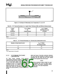
Figure 23. Technique for Measuring Case Temperature (T C) on TCP
Table 26. TCP Thermal Resistance vs. Copper Plane Thickness With and Without Enhancements
Copper
Plane
q
CA (°C/Watt)
No
qCA (°C/Watt)
With Heat Pipe and
Al Plates
Thickness*
Enhancements
1 oz. Cu
3 oz. Cu
18
14
7.8
7.8
NOTE:
*225 vias underneath the die
Table 27. TCP Thermal Resistance vs. Thermal Vias Underneath the Die
Number of Vias Under the Die*
qCA (°C/Watt)
No Enhancements
0
15
144
13
NOTE:
*3 oz. copper planes in tet boards
attach pad using a thermally conductive adhesive.
This test board was designed to optimize the heat
spreading into the board and the heat transfer
through to the opposite side of the board.
6.1.3.1.
TCP STANDARD TEST BOARD
CONFIGURATION
All Tape Carrier Package (TCP) thermal
measurements familiarity provided in the following
tables were taken with the component soldered to a
2" x 2" test board outline. This six-layer board
contains 225 vias in the die attach pad which are
connected to two 3 oz. copper planes located at
layers two and five. For the TCP, the vias in the die
attach pad should be connected without thermal
reliefs to the ground plane(s). The die is attached to
the die
NOTE
Thermal resistance values should be used
as guidelines only, and are highly system
dependent. Final system verification should
always refer to the case temperature
specification.
65

 INTEL [ INTEL ]