Electrical Specifications
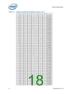
Table 2-1.
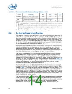
Processor Absolute Maximum Ratings (Sheet 2 of 2)
Notes
Symbol
Parameter
Min
Max
Unit
1, 2
V(ISENSE)
Analog input voltage with respect to
Vss for sensing current consumption
-0.25
1.15
V
T
T
Processor case temperature
See Chapter 6
–40
See Chapter 6
85
CASE
Processor storage temperature
°C
3, 4
STORAGE
Notes:
1.
For functional operation, all processor electrical, signal quality, mechanical, and thermal specifications must
be satisfied.
2.
3.
Excessive overshoot or undershoot on any signal will likely result in permanent damage to the processor.
Storage temperature is applicable to storage conditions only. In this scenario, the processor must not
receive a clock, and no pins can be connected to a voltage bias. Storage within these limits will not affect
the long-term reliability of the device. For functional operation, please refer to the processor case
temperature specifications.
4.
This rating applies to the processor and does not include any packaging or trays.
2.2
Socket Voltage Identification
The VID[7:0], CVID[7:1], and VIO_VID[4:1] pins identify encoding that determine the
voltage to be supplied by the VR to the socket Vcore, Vcache and VIO (the core, cache
& system interface voltages for the Intel Xeon Processor E7-8800/4800/2800 Product
Families processor) voltage regulators. The CoreVID and CacheVID specifications for
the Intel Xeon Processor E7-8800/4800/2800 Product Families processors are defined
by VR 11.1. VIO_VID specifications for the Intel Xeon Processor E7-8800/4800/2800
Product Families processors are defined by VR 11.0.
For CoreVID and CacheVID, individual processor VID values may be calibrated during
manufacturing such that two devices at the same core speed may have different
default VID settings. Furthermore, any Intel Xeon Processor E7-8800/4800/2800
Product Families processor can drive different VID settings during normal operation. For
VIO_VID, all processors of a given stepping will have the same values.
The Voltage Identification (VID) specification for the Intel Xeon Processor E7-8800/
4800/2800 Product Families processor is defined by the Voltage Regulator Module
(VRM) and Enterprise Voltage Regulator-Down (EVRD) 11.1 Design Guidelines. The
voltage set by the VID signals is the reference VR output voltage to be delivered to the
processor Vcc pins. VID signals are CMOS push/pull drivers. Please refer to Table 2-24
for the DC specifications for these signals. A voltage range is provided in Table 2-5 and
changes with frequency. The specifications have been set such that one voltage
regulator can operate with all supported frequencies.
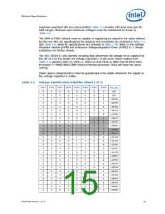
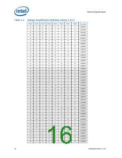
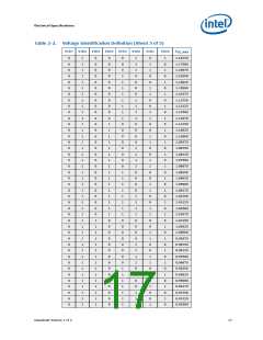
The Intel Xeon Processor E7-8800/4800/2800 Product Families processor uses eight
voltage identification signals, VID[7:0], to support automatic selection of power supply
voltages. Table 2-2 specifies the voltage level corresponding to the state of VID[7:0]. A
‘1’ in this table refers to a high voltage level and a ‘0’ refers to a low voltage level. If
the processor socket is empty (SKTOCC# high), or the voltage regulation circuit cannot
supply the voltage that is requested, the voltage regulator must disable itself. See the
Voltage Regulator Module (VRM) and Enterprise Voltage Regulator-Down (EVRD) 11.1
Design Guidelines for further details.
The Intel Xeon Processor E7-8800/4800/2800 Product Families processor provides the
ability to operate while transitioning to an adjacent VID and its associated processor
core voltage (Vcc). This will represent a DC shift in the load line. It should be noted that
a low-to-high or high-to-low voltage state change may result in as many VID
transitions as necessary to reach the target core voltage. Transitions above the
14
Datasheet Volume 1 of 2

 INTEL [ INTEL ]