Electrical Characteristics
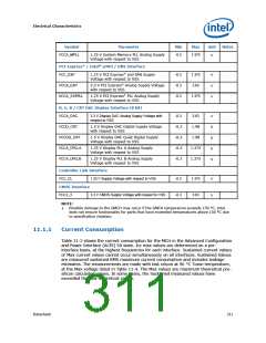
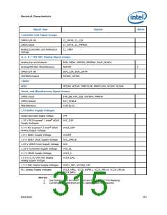
Symbol
Parameter
Min
Max
Unit
Notes
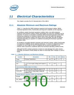
VCCA_MPLL
1.25 V System Memory PLL Analog Supply
Voltage with respect to VSS
-0.3
1.375
V
PCI Express* / Intel® sDVO / DMI Interface
VCC_EXP
1.25 V PCI Express* and DMI Supply
Voltage with respect to VSS
-0.3
-0.3
-0.3
1.375
3.63
V
V
V
VCCA_EXP
VCCA_EXPPLL
3.3 V PCI Express* Analog Supply Voltage
with respect to VSS
1.25 V PCI Express* PLL Analog Supply
Voltage with respect to VSS
1.375
R, G, B / CRT DAC Display Interface (8 bit)
VCCA_DAC
3.3 V Display DAC Analog Supply Voltage with
respect to VSS
-0.3
-0.3
-0.3
-0.3
-0.3
3.63
1.98
V
V
V
V
V
VCCD_CRT
1.5 V Display DAC Digital Supply Voltage
with respect to VSS
VCCDQ_CRT
VCCA_DPLLA
VCCA_DPLLB
1.5 V Display DAC Quiet Digital Supply
Voltage with respect to VSS
1.98
1.25 V Display PLL A Analog Supply
Voltage with respect to VSS
1.375
1.375
1.25 V Display PLL B Analog Supply
Voltage with respect to VSS
Controller Link Interface
VCC_CL
1.25 V Supply Voltage with respect to VSS
-0.3
-0.3
1.375
3.63
V
V
CMOS Interface
VCC3_3
3.3 V CMOS Supply Voltage with respect to VSS
NOTE:
1. Possible damage to the GMCH may occur if the GMCH temperature exceeds 150 °C. Intel
does not ensure functionality for parts that have exceeded temperatures above 150 °C due
to specification violation.
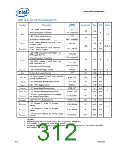
11.1.1
Current Consumption
Table 11-2 shows the current consumption for the MCH in the Advanced Configuration
and Power Interface (ACPI) S0 state. Icc max values are determined on a per-
interface basis, at the highest frequencies for each interface. Sustained current values
or Max current values cannot occur simultaneously on all interfaces. Sustained Values
are measured sustained RMS maximum current consumption and includes leakage
estimates. The measurements are made with fast silicon at 96 °C Tcase temperature,
at the Max voltage listed in Table 11-4. The Max values are maximum theoretical pre-
silicon calculated values. In some cases, the Sustained measured values have
exceeded the Max theoretical values.
Datasheet
311

 INTEL [ INTEL ]