Land Listing and Signal Descriptions
Table 25.
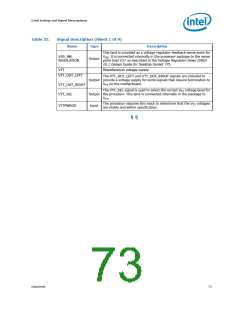
Signal Description (Sheet 1 of 9)
Name
Type
Description
INIT# (Initialization), when asserted, resets integer registers inside
the processor without affecting its internal caches or floating-point
registers. The processor then begins execution at the power-on
Reset vector configured during power-on configuration. The
processor continues to handle snoop requests during INIT#
assertion. INIT# is an asynchronous signal and must connect the
appropriate pins/lands of all processor FSB agents.
INIT#
Input
If INIT# is sampled active on the active to inactive transition of
RESET#, then the processor executes its Built-in Self-Test (BIST).
ITP_CLK[1:0] are copies of BCLK that are used only in processor
systems where no debug port is implemented on the system board.
ITP_CLK[1:0] are used as BCLK[1:0] references for a debug port
implemented on an interposer. If a debug port is implemented in the
system, ITP_CLK[1:0] are no connects in the system. These are not
processor signals.
ITP_CLK[1:0]
Input
LINT[1:0] (Local APIC Interrupt) must connect the appropriate pins/
lands of all APIC Bus agents. When the APIC is disabled, the LINT0
signal becomes INTR, a maskable interrupt request signal, and
LINT1 becomes NMI, a nonmaskable interrupt. INTR and NMI are
backward compatible with the signals of those names on the Celeron
D processor. Both signals are asynchronous.
LINT[1:0]
Input
Both of these signals must be software configured via BIOS
programming of the APIC register space to be used either as NMI/
INTR or LINT[1:0]. Because the APIC is enabled by default after
Reset, operation of these signals as LINT[1:0] is the default
configuration.
The LL_ID[1:0] signals are used to select the correct loadline slope
for the processor. LL_ID[1:0] = 00 for the Celeron D processor.
LL_ID[1:0]
LOCK#
Output
LOCK# indicates to the system that a transaction must occur
atomically. This signal must connect the appropriate pins/lands of all
processor FSB agents. For a locked sequence of transactions,
LOCK# is asserted from the beginning of the first transaction to the
end of the last transaction.
Input/
Output
When the priority agent asserts BPRI# to arbitrate for ownership of
the processor FSB, it will wait until it observes LOCK# de-asserted.
This enables symmetric agents to retain ownership of the processor
FSB throughout the bus locked operation and ensure the atomicity
of lock.
MCERR# (Machine Check Error) is asserted to indicate an
unrecoverable error without a bus protocol violation. It may be
driven by all processor FSB agents.
MCERR# assertion conditions are configurable at a system level.
Assertion options are defined by the following options:
•
•
•
Enabled or disabled.
Asserted, if configured, for internal errors along with IERR#.
Asserted, if configured, by the request initiator of a bus transaction after it
observes an error.
Input/
Output
MCERR#
•
Asserted by any bus agent when it observes an error in a bus transaction.
For more details regarding machine check architecture, refer to the
IA-32 Software Developer’s Manual, Volume 3: System
Programming Guide.
Datasheet
69

 INTEL [ INTEL ]