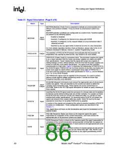
Thermal Specifications and Design Considerations
and is not representative of the absolute maximum power the processor may dissipate under worst case
conditions.
2. Not 100% tested. These power specifications are determined by characterization of the processor currents at
higher temperatures and extrapolating the values for the temperature indicated.
3. The maximum junction temperature (TJ) is specified as the hottest location on the die. The thermal monitor’s
automatic mode is used to indicate that the maximum TJ has been reached. Refer to Section 6.1.1 for TJ
measurement guidelines (Refer to Section 6.1.2 for thermal monitor details).
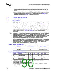
6.1
Thermal Specifications
6.1.1
Thermal Diode
The Mobile Intel Pentium 4 Processor-M incorporates two methods of monitoring die temperature,
the thermal monitor and the thermal diode. The thermal monitor (detailed in Section 6.1.2) must be
used to determine when the minimum or maximum specified processor junction temperature has
been reached. The second method, the thermal diode, can be read by an off-die analog/digital
converter (a thermal sensor) located on the motherboard, or a stand-alone measurement kit. The
thermal diode may be used to monitor the die temperature of the processor for thermal
management or instrumentation purposes but cannot be used to indicate that the maximum T of
J
the processor has been reached. Table 39 and Table 40 provide the diode interface and
specifications.
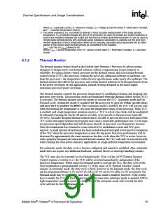
Note: The reading of the thermal sensor connected to the thermal diode does not reflect the temperature
of the hottest location on the die (T ). This is due to inaccuracies in the thermal diode, on-die
J
temperature gradients between the location of the thermal diode and the hottest location on the die,
and time based variations in the die temperature. Time based variations can occur since the
sampling rate of the sensor is much slower than the die level temperature changes.
The offset between the thermal diode based temperature reading and the hottest location of the die
(thermal monitor) may be characterized using the thermal monitor’s Automatic mode activation of
thermal control circuit. This temperature offset must be taken into account when using the
processor thermal diode to implement power management events.
Table 39. Thermal Diode Interface
Signal Name
Pin/Ball Number
Signal Description
THERMDA
THERMDC
B3
C4
Thermal diode anode
Thermal diode cathode
Table 40. Thermal Diode Specifications
Symbol
Parameter
Min
Typ
Max
Unit
Notes
IFW
n
Forward Bias Current
Diode Ideality Factor
Series Resistance
5
300
µA
1
1.0012
1.0021
3.86
1.0030
2, 3, 4
2, 3, 5
RT
ohms
NOTES:
1. Intel does not support or recommend operation of the thermal diode under reverse bias.
2. Characterized at 100°C.
3. Not 100% tested. Specified by design characterization.
4. The ideality factor, n, represents the deviation from ideal diode behavior as exemplified by the diode
equation:
IFW=Is *(e(qVD/nkT) -1)
90
Mobile Intel Pentium 4 Processor-M Datasheet

 INTEL [ INTEL ]