XMC1300
XMC1000 Family
Electrical Parameter
3.2.4
Analog Comparator Characteristics
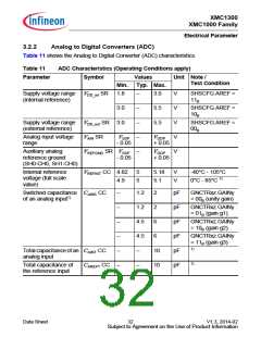
Table 13 below shows the Analog Comparator characteristics.
Table 13
Analog Comparator Characteristics (Operating Conditions apply)
Parameter
Symbol
Limit Values
Unit Notes/
Test Conditions
Min. Typ. Max.
Input Voltage
Input Offset
VCMP
SR -0.05
–
VDDP
0.05
+
V
VCMPOFF CC
–
–
–
–
–
–
–
+/-3
–
mV High power mode
Δ VCMP < 200 mV
+/-20 –
mV Low power mode2)
Δ VCMP < 200 mV
Propagation
Delay1)2)
tPDELAY
CC
25
–
–
–
–
–
ns
ns
ns
ns
High power mode,
Δ VCMP = 100 mV
80
High power mode,
Δ VCMP = 25 mV
250
700
100
Low power mode,
Δ VCMP = 100 mV
Low power mode,
Δ VCMP = 25 mV
Current
IACMP
CC
μA First active ACMP in
high power mode,
Consumption2)
ΔVCMP > 30 mV
–
66
–
μA Each additional
ACMP in high power
mode, ΔVCMP > 30 mV
–
–
10
6
–
–
μA First active ACMP in
low power mode
μA Each additional
ACMP in low power
mode
Input Hysteresis2) VHYS
Filter Delay1)2)
tFDELAY
CC
CC
–
–
15
5
–
–
mV
ns
1) Total Analog Comparator Delay is the sum of Propagation Delay and Filter Delay.
2) Not subject to production test, verified by design.
Data Sheet
36
V1.3, 2014-02
Subject to Agreement on the Use of Product Information

 INFINEON [ Infineon ]