XMC1300
XMC1000 Family
General Device Information
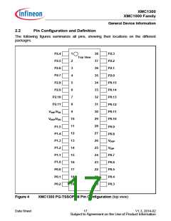
2.2
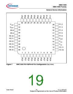
Pin Configuration and Definition
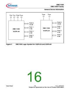
The following figures summarize all pins, showing their locations on the different
packages.
P2.4
P2.5
1
38
37
36
35
34
33
32
31
30
29
28
27
26
25
24
23
22
21
20
P2.3
Top View
2
P2.2
P2.6
3
P2.1
P2.7
4
P2.0
P2.8
5
P0.15
P0.14
P0.13
P2.9
6
P2.10
P2.11
SSP/VSS
7
8
P0.12
P0.11
P0.10
V
9
VDDP/VDD
10
11
12
13
14
15
16
17
18
19
P1.5
P1.4
P1.3
P0.9
P0.8
VDDP
P1.2
P1.1
P1.0
VSSP
P0.7
P0.6
P0.5
P0.4
P0.3
P0.0
P0.1
P0.2
Figure 4
XMC1300 PG-TSSOP-38 Pin Configuration (top view)
Data Sheet
17
V1.3, 2014-02
Subject to Agreement on the Use of Product Information

 INFINEON [ Infineon ]