TLI4946
Specification
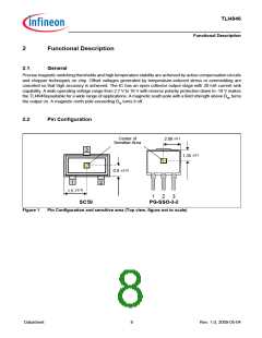
3
Specification
3.1
Application circuit
Q
Q
GND
GND
VS
200Ω
VS
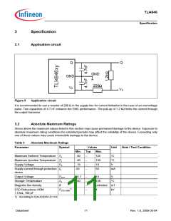
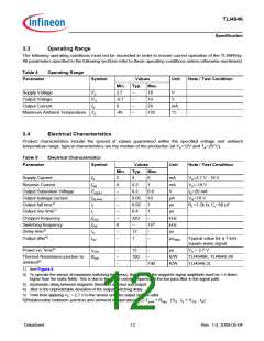
Figure 5
Application circuit
It is recommended to use a resistor of 200 Ω in the supply line for current limitation in the case of an overvoltage
pulse. Two capacitors of 4.7 nF enhance the EMC performance. The pull-up of 1.2 kΩ limits the current through
the output transistor.
3.2
Absolute Maximum Ratings
Stress above the maximum values listed in this section may cause permanent damage to the device. Exposure to
absolute maximum rating conditions for extended periods may affect the reliability of the device. Exceeding only
one of these values may cause irreversible damage to the device.
Table 3
Parameter
Absolute Maximum Ratings
Symbol
Values
Unit
Note / Test Condition
Min.
- 40
- 40
- 18
-50
Typ. Max.
Maximum Ambient Temperature TA
Maximum Junction Temperature TJ
–
–
–
–
125
150
18
°C
°C
V
Supply Voltage
VS
Supply current through protection IS
50
mA
device
Output Voltage
Storage Temperature
Magnetic flux density
ESD Robustness HBM:
1.5 kΩ, 100 pF
VOUT
TS
B
- 0.7
- 40
–
–
–
–
–
18
150
V
°C
unlimited mT
kV
1)
VESD,HBM
–
4
1) According to EIA/JESD22-A114-E
Datasheet
11
Rev. 1.0, 2009-05-04

 INFINEON [ Infineon ]