TLE9879QXA40
GPIO Ports and Peripheral I/O
14.2.2
Port 2
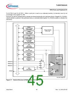
Figure 18 shows the structure of an input-only port pin. Each P2 pin can only function in input mode. Register
P2_DIR is provided to enable or disable the input driver. When the input driver is enabled, the actual voltage level
present at the port pin is translated into a logic 0 or 1 via a Schmitt trigger device and can be read via register
P2_DATA. Each pin can also be programmed to activate an internal weak pull-up or pull-down device. Register
P2_PUDSEL selects whether a pull-up or the pull-down device is activated while register P2_PUDEN enables or
disables the pull device. The analog input (AnalogIn) bypasses the digital circuitry and Schmitt trigger device for
direct feed-through to the ADC input channels.
PUDSEL
Pull-up / Pull-down
Select Register
Pull-up / Pull-down
Control Logic
I
N
T
E
R
N
A
L
PUDEN
Pull-up / Pull-down
Enable Register
Pull Device
B
U
S
Input
Driver
In
Data
Data Register
Schmitt
Trigger
Pad
AltDataIn
AnalogIn
Port_Input_Diagram.vsd
Figure 18 General Structure of Input Port (P2)
Data Sheet
46
Rev. 1.0, 2015-04-30

 INFINEON [ Infineon ]