TLE9879QXA40
Interrupt System
12
Interrupt System
12.1
Features
•
•
•
Up to 16 interrupt nodes for on-chip peripherals
Up to 8 NMI nodes for critical system events
Maximum flexibility for all 16 interrupt nodes
12.2
Introduction
12.2.1
Overview
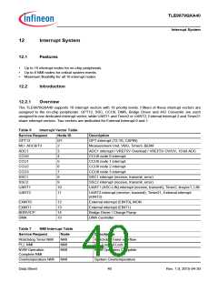
The TLE9879QXA40 supports 16 interrupt vectors with 16 priority levels. Fifteen of these interrupt vectors are
assigned to the on-chip peripherals: GPT12, SSC, CCU6, DMA, Bridge Driver and A/D Converter are each
assigned to one dedicated interrupt vector; while UART1 and Timer2 or UART2, External Interrupt 2 and Timer21
share interrupt vectors. Two vectors are dedicated for External Interrupt 0 and 1.
Table 6
Interrupt Vector Table
Service Request
GPT12
Node ID
Description
0/1
2
GPT interrupt (T2-T6, CAPIN)
MU- ADC8/T3
ADC1
Measurement Unit, VBG, Timer3, BEMF
ADC1 interrupt / VREF5V Overload / VREF5V OV/UV, 10-bit ADC
CCU6 node 0 interrupt
3
CCU0
4
CCU1
5
CCU6 node 1 interrupt
CCU2
6
CCU6 node 2 interrupt
CCU3
7
CCU6 node 3 interrupt
SSC1
8
SSC1 interrupt (receive, transmit, error)
SSC2 interrupt (receive, transmit, error)
UART1 (ASC-LIN) interrupt (receive, transmit), Timer2, linsync1, LIN
SSC2
9
UART1
UART2
10
11
UART2 interrupt (receive, transmit), Timer21, External interrupt
(EINT2)
EXINT0
EXINT1
BDRV/CP
DMA
12
13
14
15
External interrupt (EINT0), MON
External interrupt (EINT1)
Bridge Driver / Charge Pump
DMA Controller
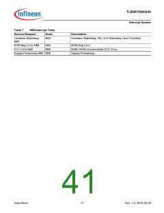
Table 7
NMI Interrupt Table
Service Request
Watchdog Timer NMI
PLL NMI
Node
NMI
NMI
NMI
Description
Watchdog Timer overflow
PLL Loss-of-Lock
NVM Operation
Complete NMI
NVM Operation Complete
Overtemperature NMI
NMI
System Overtemperature
Data Sheet
40
Rev. 1.0, 2015-04-30

 INFINEON [ Infineon ]