TLE9879QXA40
Power Management Unit (PMU)
5.2.1
Block Diagram
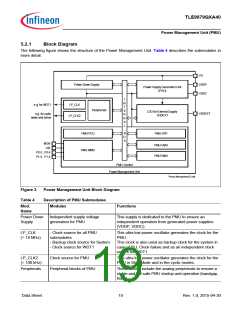
The following figure shows the structure of the Power Management Unit. Table 4 describes the submodules in
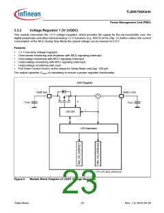
more detail.
VS
Power Down Supply
VDDP
VDDC
Power SupplyGeneration Unit
(PGU)
I
N
T
E
R
N
A
L
e.g. for WDT1
LP_CLK
Peripherals
LDO for External Supply
VDDEXT
VDDEXT
e.g. for cyclic
wake and sense
LP_CLK2
B
U
S
PMU-PCU
PMU-SFR
MON
LIN
P0.0...P0.4
P1.0...P1.4
PMU-CMU
PMU-RMU
PMU-WMU
PMU-Control
Power Management Unit
Power_Management_7x.vsd
Figure 3
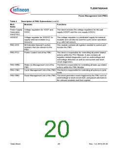
Table 4
Power Management Unit Block Diagram
Description of PMU Submodules
Mod.
Modules
Functions
Name
Power Down
Supply
Independent supply voltage
generation for PMU
This supply is dedicated to the PMU to ensure an
independent operation from generated power supplies
(VDDP, VDDC).
LP_CLK
(= 18 MHz)
- Clock source for all PMU
submodules
This ultra low power oscillator generates the clock for the
PMU.
- Backup clock source for System
- Clock source for WDT1
This clock is also used as backup clock for the system in
case of PLL Clock failure and as an independent clock
source for WDT1.
LP_CLK2
(= 100 kHz)
Clock source for PMU
This ultra low power oscillator generates the clock for the
PMU in Stop Mode and in the cyclic modes.
Peripherals
Peripheral blocks of PMU
These blocks include the analog peripherals to ensure a
stable and fail-safe PMU startup and operation (bandgap,
bias).
Data Sheet
19
Rev. 1.0, 2015-04-30

 INFINEON [ Infineon ]