OPTIREG™ SBC TLE9274QXV33
LIN transceiver
9.2
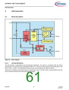
Functional description
The LIN bus is a single wire, bidirectional bus, used for in-vehicle networks. The LIN transceivers implemented
inside the TLE9274QXV33 are the interface between the microcontroller and the physical LIN bus. The digital
output data from the microcontroller are driven to the LIN bus via the TXDLIN input pin on the TLE9274QXV33.
The transmit data stream on the TXDLIN input is converted to a LIN bus signal with an optimized slew rate to
minimize the EME level of the LIN network. The RXDLIN output sends back the information from the LIN bus to
the microcontroller. The receiver has an integrated filter network to suppress noise on the LIN bus and to
increase the EMI (Electromagnetic Immunity) level of the transceiver.
Two logical states are possible on the LIN bus according to the LIN Specification 2.2.
Every LIN network consists of a master node and one or more slave nodes. To configure the TLE9274QXV33 for
master node applications, a resistor in the range of 1 kΩ and a reverse diode must be connected between the
LIN bus and the power supply VS.
The different transceiver modes can be controlled using the SPI LIN2, LIN3 and LIN4 bits.
The transceiver can also be configured to wake capable in order to save current and to ensure a safe transition
from SBC Normal to Sleep mode (to avoid losing messages).
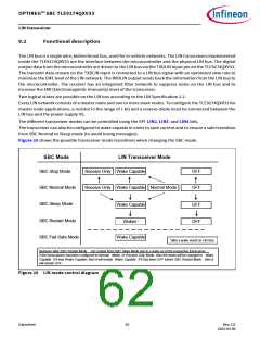
Figure 25 shows the possible transceiver mode transitions when changing the SBC mode.
SBC Mode
LIN Transceiver Mode
SBC Stop Mode
Receive Only Wake Capable
OFF
OFF
SBC Normal Mode
SBC Sleep Mode
SBC Restart Mode
SBC Fail-Safe Mode
Receive Only Wake Capable Normal Mode
Wake Capable
OFF
OFF
Woken1
Wake Capable
1after a wake event on LIN Bus
Behavior after SBC Restart Mode - not coming from SBC Sleep Mode due to a wake up of the respective transceiver
:
If the transceivers had been configured to Normal Mode, or Receive Only Mode, then the mode will be changed to Wake
Capable. If it was Wake Capable, then it will remain Wake Capable . If it had been OFF before SBC Restart Mode , then it
will remain OFF .
Figure 25 LIN mode control diagram
Datasheet
62
Rev.2.0
2022-05-06

 INFINEON [ Infineon ]