TLE 6244X
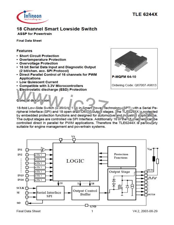
All low side switches are equipped with fault diagnostic functions:
- short-circuit to UBatt (SCB) can be detected if switches are turned on
:
- short-circuit to ground: (SCG) can be detected if switches are turned off
- open load:
(OL) can be detected if switches are turned off
(OT) will only be detected if switches are turned on
- overtemperature:
The fault conditions SCB, SCG, OL and OT will not be stored until an integrated filtering time is
expired (please note for PWM application). If, at one output, several errors occur in a sequence,
always the last detected error will be stored (with filtering time). All fault conditions are encoded
in two bits per switch and are stored in the corresponding SPI registers. Additionally there are
two central diagnostic bits: one specially for OT and one for fault occurrence at any output.
The registers can be read out via SPI. After each read out cycle the registers have to be cleared
by the DEL_DIA command.
1.3.1 Power Stage OUT8 (Condensed Description)
1.3.1.1 Control of OUT8 and VDD-Monitoring
OUT8 can be controlled by SPI or by the pin IN8 only, control by µs-bus is not possible. When
controlled by IN8 this power stage is functional if the voltage at the pin VDD is above 3,5V. In
SPI mode the power stage is fully supervised by the VDD-monitor.
If OUT8 is controlled by IN8, OUT8 will only be switched off by the overvoltage detection and
not by undervoltage detection.
1.3.1.2 Phase Relation IN8 - OUT8
The phase relation IN8 -> OUT8 is inverting.
OUT8 is active if IN8 is set to logic '1' (high level, see 3.4.2 ) in case of parallel access.
On executing the read instruction on RD_INP1/2 the inverted status of IN8 is read back.
1.3.1.3 Reset / Power Stage Diagnostics
If OUT8 is controlled by IN8, OUT8 will not be reseted by RST.
After reset parallel control (by IN8) is active for OUT8.
If UVDD < 4.5V errors are not stored because of the active RST of the external Regulator. Nev-
ertheless
OUT8 is protected against overload.
1.3.1.4 Input Current
The control input IN8 has an internal pull-down current source. Thus the input currents I IN8
are positive (flow into the pin).
1.3.1.5 On Resistance
For OUT8 and 3.5V < UVDD < 4.5V R on increases (see 3.8.5).
1.3.1.6 Parallel Connection of Power Stages
Parallel connection of power stages with OUT8 and parallel control is prohibited (inverting
input IN8). Control via SPI is possible. See 1.13.
Final Data Sheet
5
V4.2, 2003-08-29

 INFINEON [ Infineon ]