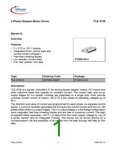
TLE 4726
Pin Definitions and Functions
Pin No.
Function
1, 2, 23, 24
Digital control inputs IX0, IX1 for the magnitude of the current of the
particular phase.
IX1
IX0 Phase
Example of
Current
Motor Status
H
H
L
H
L
0
No current
Hold
1/3 Imax
2/3 Imax
Imax
typical Imax with
sense = 1 Ω: 750 mA
R
H
L
Set
L
Accelerate
3
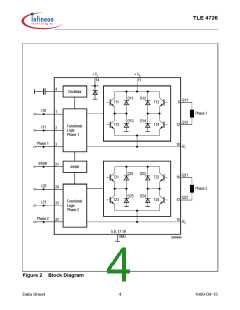
Input Phase 1; controls the current through phase winding 1. On
H-potential the phase current flows from Q11 to Q12, on L-potential in
the reverse direction.
5, 6, 7, 8, 17, Ground; all pins are connected internally.
18, 19, 20
4
Oscillator; works at approx. 25 kHz if this pin is wired to ground across
2.2 nF.
10
Resistor R1 for sensing the current in phase 1.
9, 12
Push-pull outputs Q11, Q12 for phase 1 with integrated free-wheeling
diodes.
11
14
Supply voltage; block to ground, as close as possible to the IC, with a
stable electrolytic capacitor of at least 10 µF in parallel with a ceramic
capacitor of 220 nF.
Logic supply voltage; either supply with 5 V or connect to + VS across
a series resistor. A Z-diode of approx. 7 V is integrated. In both cases
block to ground directly on the IC with a stable electrolytic capacitor of
10 µF in parallel with a ceramic capacitor of 100 nF.
13, 16
Push-pull outputs Q22, Q21 for phase 2 with integrated free-wheeling
diodes.
15
21
Resistor R2 for sensing the current in phase 2.
Inhibit input; the IC can be put on standby by low potential on this pin.
This reduces the current consumption substantially.
22
Input phase 2; controls the current flow through phase winding 2. On
H-potential the phase current flows from Q21 to Q22, on L potential in
the reverse direction.
Data Sheet
3
1999-09-15

 INFINEON [ Infineon ]