TLD7002-16ES
Datasheet
9 Communication interface
9.1.11.6
PM_CHANGE - power mode change
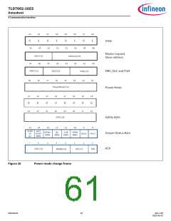
The purpose of the master request frame power mode change is to initiated a transition to the commanded power
state. The data transfer to the slave is organized in dedicated write frame, containing
•
•
•
•
•
•
•
the sync byte, provided by the master,
the address byte, provided by the master,
the MRC_DLC_FUN byte, provided by the master,
the power mode provided by the master,
the safety byte (CRC-8), provided by the master,
the output status byte, provided by the slave and the
Acknowledge byte (ACK) provided by the slave.
The slave response bytes "output status byte and acknowledge byte" are skipped in case the power mode change is
sent to the broadcast address. Consequently there is no response from the slave to the master given in case of the
broadcast address contains the power mode change frame.
The PM_CHANGE frame requires following field configurations to perform the power mode change:
•
•
DLC[5:3] = 0x1 for 1 word respectively 2 bytes
FUN[2:0] = 0x6
The slave ignores and discards frames in case of an unexpected DLC or FUN data as described in Chapter 9.1.11.10.
The master request CRC[7:5] is calculated as described in CRC-3 for master requests.
The safety byte CRC[7:0] is calculated as described in CRC-8 for safety byte.
The slave response CRC[7:5] is calculated as described in CRC-3 for slave response.
Datasheet
60
Rev.1.00
2022-05-03

 INFINEON [ Infineon ]